Connection definition
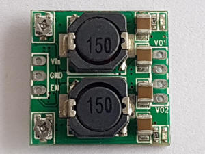
Input pin 1.Vin: positive input |
| Output pin: 1.VO1: First channel output is positive Note: Input and output are commonly available |
How to use the power supply
Using the module is very simple. First, it's recommended to solder pin strips to the PCB pads to facilitate connecting the cables. If you plan to use the module inside a container, you can solder the cables directly to the pads.
|
|
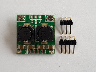

Once the connections have been made and the power has been supplied, the two LEDs on the module should be lit. Now the two small trimmers on the PCB need to be calibrated, one for each channel.
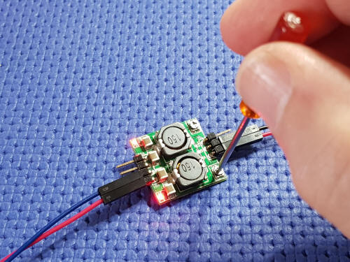
At this point, using a small screwdriver, you'll need to gently rotate the trimmer for the relevant channel. The value will be measured using a digital multimeter. Various adjustments are necessary, as the value may vary slightly when the screwdriver is removed. Once the calibration is complete, the module is calibrated.
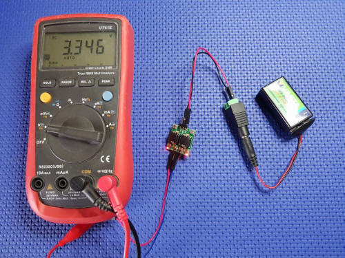
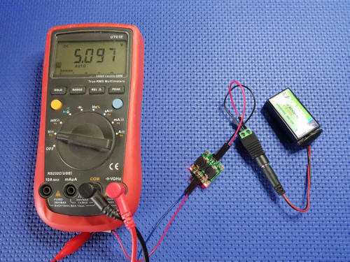
In the examples below, the two channels have been set to provide voltages of 3.3V and 5V; small variations do not affect the operation of the circuits connected to the power supply module.
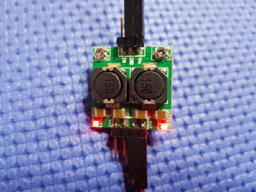
At this point, using a small flathead screwdriver, you'll need to gently rotate the trimmer for the relevant channel. The value will be measured using a digital multimeter. Various adjustments are necessary, as the value may vary slightly when the screwdriver is removed. Once the calibration is complete, the module is calibrated
In the examples below, the two channels have been set to provide voltages of 3.3V and 5V; small variations do not affect the operation of the circuits connected to the power supply module.