Features:
- Load voltage, supports rated 1-22V LD, can also provide 36V version, supports higher voltage.
- Load current, up to 5A.
- Low ripple, low temperature drift, high reliability.
- No heat generation, no need to consider heat dissipation during use.
- Adaptive load voltage, from a single tube to approaching the supply voltage.
- High speed, rising and falling edge < 1ms.
- Two analog channels are optional (internal and external control, one of which is a slow interface that can be connected to analog or potentiometer).
- Switching the channel to a high-speed analog switch can achieve modulation function.
- Small size, easy to integrate.
Recommended Application:
- DP/SPSL end-pump/side-pump laser.
- Diode Laser semiconductor laser.
- Fiber lasers.
- CW or Pulsed Applications: various products that require constant current output, such as semiconductor laser testing, LED light emitting diode testing, etc.
- Applications such as welding, marking, heating, product testing, etc.
Specification:
- Model: LDSS-0.5A-MA
- Load current: rated 5A max, designated by the user (optional)
- Load voltage: 22V max at 24V PVDD. Suggest to be at least 10% lower than the supply voltage.
- Rising/falling time: <1ms
- Current ripple: < 1%
- Current temperature drift: < 100ppm
- Efficiency: >96%
- Input voltage:
12 - 24V: at least 1V higher than the maximum voltage of the load, it is recommended to use a standard power supply of 12/15/24V.
36V: when using the 36V version.
- Current analog input: 0 - 5V, corresponding to 0 - maximum current
- Current feedback output: 0 - 2.5V, corresponding to 0 - maximum current
- Storage temperature: -40 ~ +80℃
- Working temperature: -10 ~ +60℃
- Working humidity: 0 - 99%
- Size: 70 x 54 x 25mm (onboard 20mm, board thickness of 1.5mm)
Examples of applicable products:
- For NLIGHT, OCLARO, BWT...
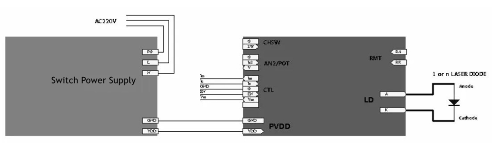
Interface Definition:
- PVDD: power input port/5.0mm wiring terminal
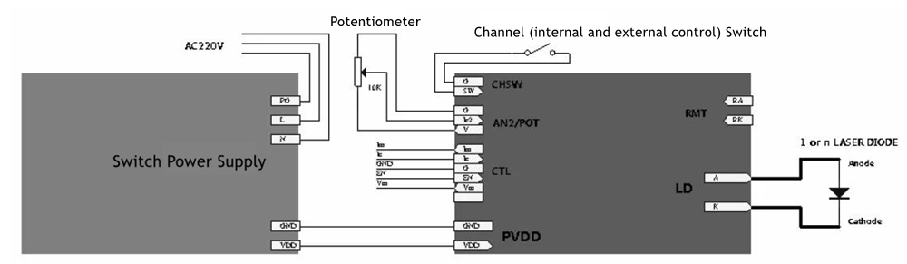
- AN2/POT: second channel analog input terminal, can be connected to potentiometer or analog/2510-3P socket
- CHSW: channel (internal and external control) selection, and if not connected, use the analog input of the CTL interface by default
- CTL: control terminal/2510-6P socket
- LD: output port/5.0mm terminal block
A: Connect the positive pole of the load LD
K: Connect the negative pole of the load LD
Different Application Configurations:
- For applications that only require one analog signal to directly control the output current of the driver board, only the CTL interface can be used to control the driver board, and AN2/POT and CHSW interfaces are not connected to any signals.
- For applications that require internal and external control, such as a power box that has both local signals and external analog signal input ports. Local signals are usually provided by potentiometers or generated by local micro-controllers, while external control signals are provided by the user of the enclosure. At this point, CTL's IC can be used to connect external analog signals, AN2/POT can be directly connected to a 10K (1K-100K is fine) potentiometer, or a local analog signal generated by the IC2 microcontroller, and then CHSW's SW can be used to switch between internal and external control.
- For applications that require fast modulation of current (such as power switches in fiber lasers), CTL's IC input current signal and AN2/POT's IC2 input threshold current signal can be used, and then TTL signal can be directly used to output CHSW's SW to modulate the current. Of course, direct modulation of analog signals, that is, using only ICs with rapidly changing analog inputs, is also possible.
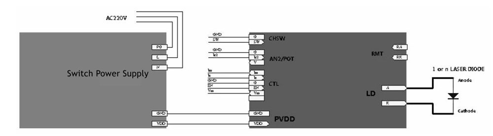
- Note: during modulation, it is generally not adjusted between 0A and the operating current, but rather from the threshold to the operating current. If the current is 0A, it is not good for the laser diode first, because without a maintained threshold current, the thermal shock will be greater, which is unfavorable for the laser diode. Secondly, the debugging performance is also poor, which not only prolongs the time for the current to rise, but also generates extra response time, thereby reducing the modulation speed.
Package Included:
- 1 x LD Power Board
2. We ship to your eBay or Paypal address. Please make sure your eBay and Paypal address is correct before you pay.
2. For remote regions of DHL/FedEx..., extra shipping costs might be charged. Usually it costs about 30USD-50USD. We will contact you if shipping company informed us your address belongs to remote area. Thanks for your understanding.
2. Please check with your country's customs office and inform us what/how much should declare before shipping.
2. If you are dissatisfied for any reason, please don't be quick to leave us neutral or negative feedback. We work hard to make sure EVERY CUSTOMER 100% SATISFIED and resolve any problem for you and always leave positive feedback to all our customers.
On Jul 1, 2025 at 23:38:02 PDT, seller added the following information: