|
|
JDS2900 series Dual-channel Function Signal generator combines multiple functions in one, such as Function Signal Generator, Arbitrary Waveform Generator, Pulse Generator, Sweep, Counter and Frequency Meter, etc. The instrument adopts the Direct Digital Synthesizer(DDS) technology and provides stable, precise, pure and low distortion signals. It's a great testing or measuring instrument for electronics engineers, electronic laboratory, teaching and researching. |


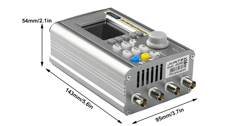
►320*240 2.4" TFT color LCD display, simultaneously display parameters of CH1 and CH2. ►Can reproduce patterns of custom waveform. ►Use soft silicone keys with high sensitivity and convenient for operation. ►Completely independent dual channels output, synchronizing operation ►60 groups of arbitrary wave storage function, memory depth of each group is 2048*14bits. ►High frequency accuracy and resolution: frequency accuracy up to 10^(-6) magnitude, total range frequency resolution is 0.01uHz. ►High amplitude resolution: the minimum amplitude resolution can reach 1mV, amplitude range is 2mVpp~20Vpp. ►Duty-cycle of each channel can be adjusted independently, the adjusting resolution is 0.1%. ►Sweep function: linear sweep and logarithmic sweep functions; 0.1s-999.9s sweep time; forward, backward and roundtrip sweep directions. ►With pulse trains burst output function: allow the unit output 1~1048575 arbitrary pulse trains. ►Measurement functions: can measure signal frequency, cycle, positive/negative pulse width and duty cycle; 1Hz~100MHz frequency range. ►With digital signal output function, CMOS output range 0~10V. ►Storage feature: can store 100 groups of parameters set by the user and extract at any time. ►Arbitrary wave editing function: user can edit arbitrary wave on PC and then download to output from the instrument. ►Communication function: the PC can be used to control the instrument. ►With output short-circuit protection: all signal output can work 60s under load short-circuit condition. ►The model sold on this link is JDS2900-60M,The maximum sine wave frequency is 60MHz, and the maximum square wave is 25MHz, 266MSa/s sampling rate and 14bits vertical resolution. |

Frequency Characteristics | ||||||||||
JDS2900-15M | JDS2900-30M | JDS2900-40M | JDS2900-50M | JDS2900-60M | ||||||
Sine wave frequency range | 0~15MHz | 0~30MHz | 0~40MHz | 0~50MHz | 0~60MHz | |||||
Square wave frequency range | 0~15MHz | 0-25MHz | 0-25MHz | 0-25MHz | 0-25MHz | |||||
Triangle wave frequency range | ||||||||||
Pulse wave frequency range | 0~6MHz | 0~6MHz | 0~6MHz | 0~6MHz | 0~6MHz | |||||
TTL digital wave frequency range | ||||||||||
Arbitrary frequency range | ||||||||||
Pulse width adjustment range | 100nS~4000S | 50nS~4000S | 40nS~4000S | 30nS~4000S | 25nS~4000S | |||||
Square wave rise time | ≤25ns | ≤15ns | ≤10ns | ≤10ns | ≤10ns | |||||
Minimum frequency resolution | 0.01uHz(0.00000001Hz) | |||||||||
Frequency accuracy | ±20ppm | |||||||||
Frequency stability | ±1ppm/3hours | |||||||||
Waveform characteristics | ||||||||||
Waveform type | SineSquare、pulse (adjustable duty cycle, precise adjustment of pulse width and period), triangular wave, partial sine wave, CMOS wave, DC level (set DC amplitude by adjusting offset), half wave, full Wave, positive staircase wave, anti-ladder wave, noise wave, exponential rise, exponential drop, multisonic wave, Symplectic pulse and Lorenz pulseand 60 arbitrarywave forms. | |||||||||
Wave length | 2048 points | |||||||||
Waveformsampling rate | 266MSa/s | |||||||||
Waveform vertical resolution | 14-bits | |||||||||
Square wave and pulse wave | Overshoot | ≤5% | ||||||||
Pulse wave | Duty cycle adjustment range | 0.1%~99.9% | ||||||||
Partial sine wave | Duty cycle adjustment range | 0.1%~99.9% | ||||||||
Sine wave | Harmonic Suppression | ≥45dBc(<1MHz); ≥40dBc(1MHz~20MHz) | ||||||||
Total harmonic distortion | <1%(20Hz~20kHz,0dBm) | |||||||||
Saw-tooth wave | Linearity | ≥98%(0.01Hz~10kHz) | ||||||||
Output characteristics | ||||||||||
Sine wave amplitude range | Frequency < 11MHz | 11MHz ≤ Frequency < 31MHz | 31MHz ≤ Frequency | |||||||
2mVpp~20Vpp | 2mVpp~10Vpp | 2mVpp~5Vpp | ||||||||
Squarewave/Triangle wave amplitude range | Frequency ≤ 10MHz | 10MHz ≤Frequency ≤25MHz | ||||||||
2mVpp~20Vpp | 2mVpp~10Vpp | |||||||||
Amplituderesolution | 1mV | |||||||||
Amplitudestability | ±0.5%/5 hours | |||||||||
Flatness ofamplitude | ±5%(<10MHz); ±10%(>10MHz) | |||||||||
Waveform output | ||||||||||
Outputimpedance | 50Ω±10% (typical) | |||||||||
Protection | All signal outputs can work within 60 seconds when the load is short-circuited. | |||||||||
DC offset | ||||||||||
Offsetadjustment range | |Offset|≤10-ampilitude/2 | |||||||||
Offset resolution | 0.01 V | |||||||||
Phase characteristics | ||||||||||
Phaseadjustment range | 0~359.9° | |||||||||
Phase resolution | 0.1° | |||||||||
TTL/CMOS output | ||||||||||
Low level | <0.3V | |||||||||
High level | 1V~10V | |||||||||
Level rise/fall time | ≤20ns | |||||||||
External measurement function | ||||||||||
Frequencymeter function | Frequency measurement range | 1Hz~100MHz | ||||||||
Measurement accuracy | Gate time 0.01S~10s continuously adjustable | |||||||||
Counter function | Counting range | 0-4294967295 | ||||||||
Coupling method | DC and AC coupling methods | |||||||||
Counting method | Manually | |||||||||
Input signal voltage range | 2Vpp~20Vpp | |||||||||
Pulse width measurement | 0.01us resolution, measure up to 20s | |||||||||
Period measurement | 0.01us resolution, measure up to 20s | |||||||||
Sweep function | ||||||||||
Sweep channel | CH1 or CH2 | |||||||||
Sweep type | Linear sweep, logarithmic sweep | |||||||||
Sweep time | 0.1s~999.9s | |||||||||
Setting range | Any setting between the maximum output frequency of the corresponding model of the starting point (0.01Hz) and the end point | |||||||||
Sweep direction | Forward, reverse and round trip | |||||||||
Bursting function | ||||||||||
Number of pulses | 1-1048575 | |||||||||
Burst mode | Manual burst, CH2 burst, external burst (AC), external burst (DC) | |||||||||
General specifications | ||||||||||
Display | Display type | 2.4 inch TFT color LCD display | ||||||||
Store and load | Quantity | 100 | ||||||||
Position | 00 to 99 (00 memory location parameter is loaded by default as power on) | |||||||||
Arbitrary wave | Quantity | 1 to 60 total 60 groups (15 groups by default as power on) | ||||||||
Interface | Interface mode | USB to serial interface | ||||||||
Extension interface | With TTL level mode serial interface for user secondary development | |||||||||
Communication speed | Adopt standard 115200bps | |||||||||
Protocol | Using the command line, the protocolis made public | |||||||||
Power supply | Voltage range | DC5V±0.5V | ||||||||
Manufacturing technology | Surface mount technology, large-scale integrated circuits, high reliability, long service life | |||||||||
Prompt tone | Users can turn on or off by setting program | |||||||||
Operating characteristics | All key operations, knob continuous adjustment | |||||||||
Environmental conditions | Temperature: 0~40℃ Humidity: <80% | |||||||||


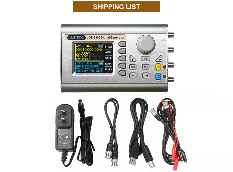
1. DDS Signal Generator*1
2. Power Adapter(In:100~240V~50/60Hz,Out:5.0V-0.2A)*1 3. BNC-BNC Cable*1
