
Store Categories
Details
Features:
1. DC-DC automatic voltage boosting module, with a wide input voltage range (3-23V), suitable for various power supply scenarios.
2. Fixed voltage output is optional, with a maximum output current of 5A, supporting high-power devices.
3. Operating frequency of 500KHz, full load ripple less than 100mV, stable and reliable output.
4. It is recommended to keep the usage within 3A for a long time, and increase heat dissipation if it exceeds 3A to ensure the lifespan of the module.
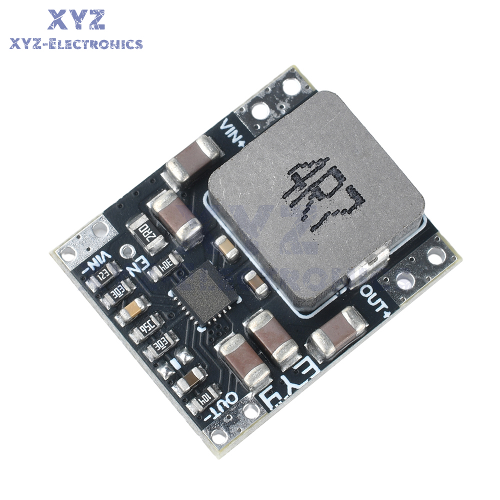
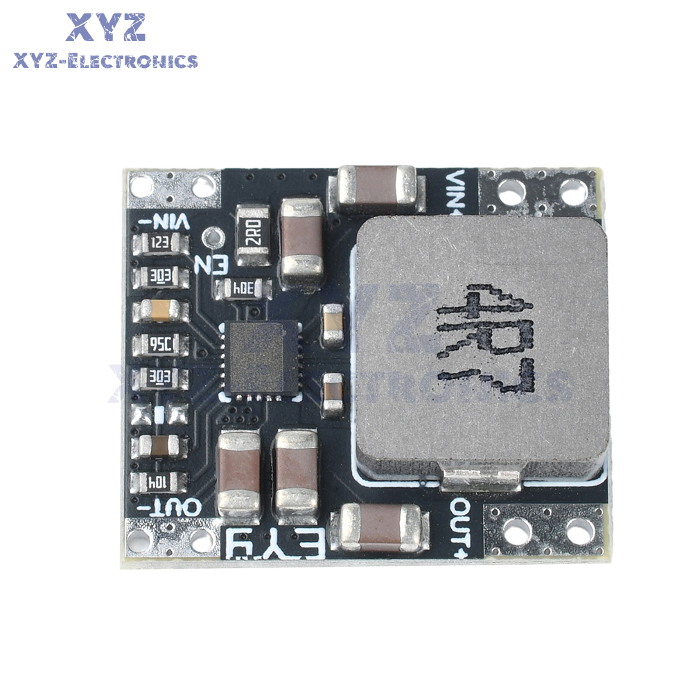
5. Compact in size, with a double hole spacing of 2.54mm, suitable for wire bonding or PCB mounting.
Parameter:
Type: DC-DC power module
Input voltage: 3-23V (minimum input voltage of 2.6V to start the chip, discharge to 2.4V to stop output) The smaller the input and output voltage difference, the lower the heat generation and the higher the efficiency.
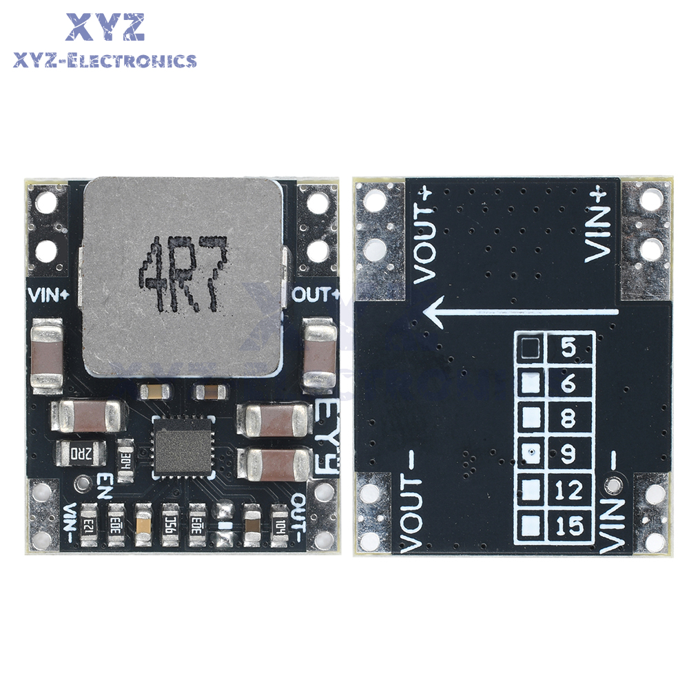
Output voltage: 5V/9V/12V fixed voltage output (non adjustable)
Output current: Maximum 5A (long-term use should be controlled within 3A with a power of 25W. If the power exceeds this limit, please increase heat dissipation. It is recommended to attach the back of the board to the outer shell of an iron or aluminum plate to increase heat dissipation, and be careful not to short-circuit underneath)
Full load ripple:<100MV (220UF electrolytic capacitor filter can be connected in parallel at the output end)
Working frequency: 500KHZ
Input current: maximum 4A
Output current: maximum 5A
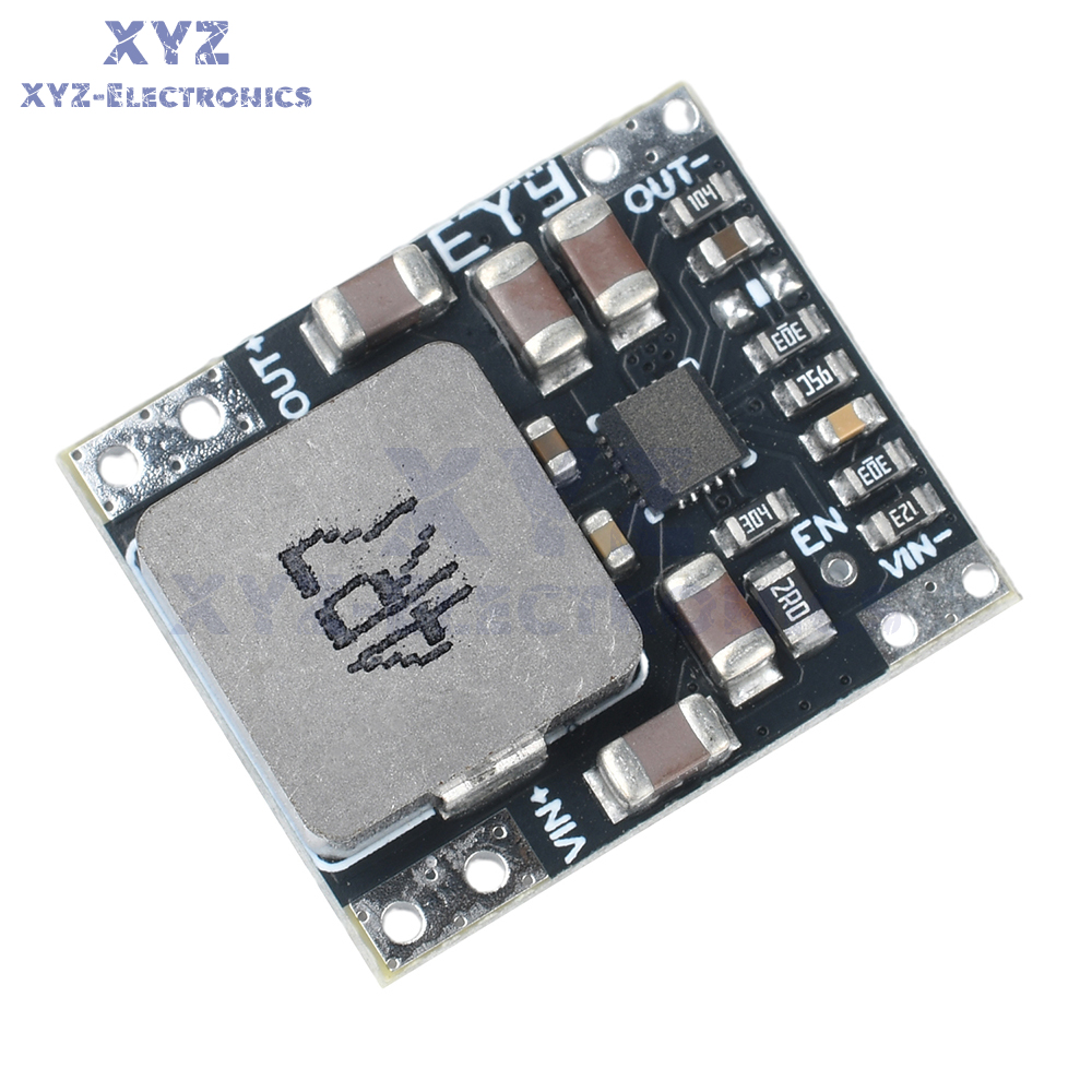
Size: 20 L * 17 W * 5.6 H MM
Package Include:
1X module
Module description and usage precautions:
1. The spacing between the dual holes of the module is 2.54MM
2. Can be attached to PCB board for use
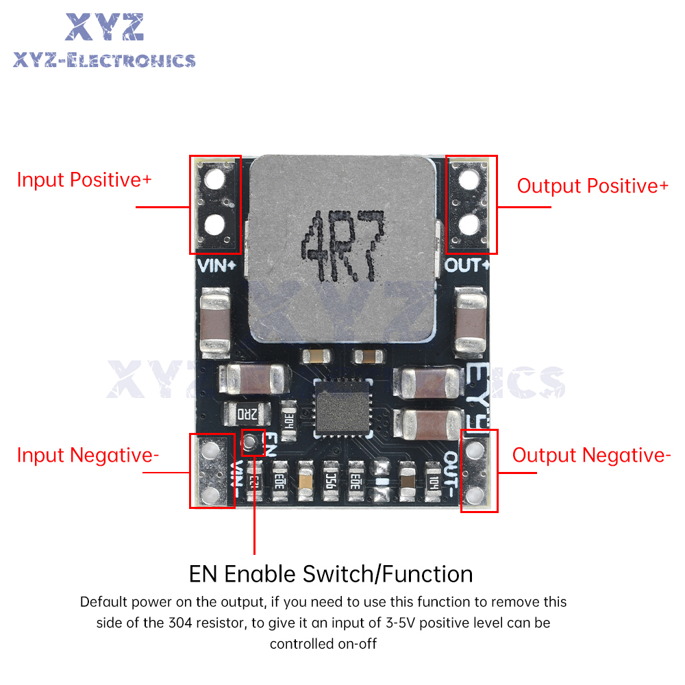
3. The negative pole of the module is common ground
4. Do not connect the input terminal to the opposite positive and negative poles, as doing so will cause overheating.
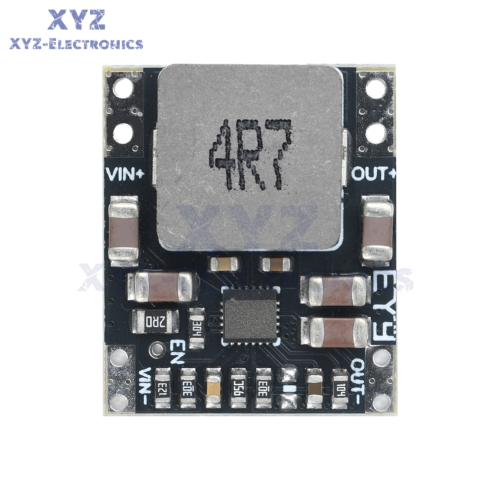
5. The solder pads on the front of the module are relatively small, so be careful not to touch inductors and other
components during soldering as it may burn the chip
6. If using boost mode, ensure reliable welding of the wiring, with short and thick wires to ensure sufficient input current.
7. Connect a 470UF/25V electrolytic capacitor in parallel at the input of the module (near the module) and connect 100UF or 220UF/25V in parallel at the output of the module
8. This module is not suitable for inductive loads such as motor relays, speakers, etc. Reverse voltage will break down the chip, and you can search online for the reverse electromotive force of principle one motor. Here is just a solution: it requires parallel TVS tubes or diodes at the output end. Try to choose a large package (TVS tube has a service life) (bidirectional TVS tube, the voltage of TVS tube is 2 volts higher than the output voltage, a little larger is also acceptable)+electrolytic capacitor 100UF or 220UF is used in parallel.
This is the description of Payment Method.
Do not dismiss your dream.
To be without dream is to be without hope.
To be without hope is to be without purpose.
Do not run through your life so fast that you forget not only where you have been, but also where you are
going.
Life is not race, but a journey to be savored each step of the way.
This is the description of Returns Policy.
Do not dismiss your dream.
To be without dream is to be without hope.
To be without hope is to be without purpose.
Do not run through your life so fast that you forget not only where you have been, but also where you are
going.
Life is not race, but a journey to be savored each step of the way.
Copyright©2017 DataCaciques
Details
Features:
1. DC-DC automatic voltage boosting module, with a wide input voltage range (3-23V), suitable for various power supply scenarios.
2. Fixed voltage output is optional, with a maximum output current of 5A, supporting high-power devices.
3. Operating frequency of 500KHz, full load ripple less than 100mV, stable and reliable output.
4. It is recommended to keep the usage within 3A for a long time, and increase heat dissipation if it exceeds 3A to ensure the lifespan of the module.
5. Compact in size, with a double hole spacing of 2.54mm, suitable for wire bonding or PCB mounting.
Parameter:
Type: DC-DC power module
Input voltage: 3-23V (minimum input voltage of 2.6V to start the chip, discharge to 2.4V to stop output) The smaller the input and output voltage difference, the lower the heat generation and the higher the efficiency.
Output voltage: 5V/9V/12V fixed voltage output (non adjustable)
Output current: Maximum 5A (long-term use should be controlled within 3A with a power of 25W. If the power exceeds this limit, please increase heat dissipation. It is recommended to attach the back of the board to the outer shell of an iron or aluminum plate to increase heat dissipation, and be careful not to short-circuit underneath)
Full load ripple:<100MV (220UF electrolytic capacitor filter can be connected in parallel at the output end)
Working frequency: 500KHZ
Input current: maximum 4A
Output current: maximum 5A
Size: 20 L * 17 W * 5.6 H MM
Package Include:
1X module
Module description and usage precautions:
1. The spacing between the dual holes of the module is 2.54MM
2. Can be attached to PCB board for use
3. The negative pole of the module is common ground
4. Do not connect the input terminal to the opposite positive and negative poles, as doing so will cause overheating.
5. The solder pads on the front of the module are relatively small, so be careful not to touch inductors and other
components during soldering as it may burn the chip
6. If using boost mode, ensure reliable welding of the wiring, with short and thick wires to ensure sufficient input current.
7. Connect a 470UF/25V electrolytic capacitor in parallel at the input of the module (near the module) and connect 100UF or 220UF/25V in parallel at the output of the module
8. This module is not suitable for inductive loads such as motor relays, speakers, etc. Reverse voltage will break down the chip, and you can search online for the reverse electromotive force of principle one motor. Here is just a solution: it requires parallel TVS tubes or diodes at the output end. Try to choose a large package (TVS tube has a service life) (bidirectional TVS tube, the voltage of TVS tube is 2 volts higher than the output voltage, a little larger is also acceptable)+electrolytic capacitor 100UF or 220UF is used in parallel.

1.We only ship to the confirmed address provided by eBay. please make sure your ebay address is 100% matches the address you would like us to ship to. If not, please let us know before we sent you the package, or we will not be responsible for any loss. hope you could understand.
2.Orders will be processed instantly and dispatched within 1-2 business days except hoilday, so we do NOT accept any email/message note after you place orders.
3.All package need to wait 30 days,Please take care it.Less than 30 days,we can't take a refund.
1.We accept PayPal payment ONLY, and must be received within 5 days from the date of purchase.
2. It is easy and safe for you to pay by credit cards, debit cards, bank transfers and PayPal account balances.
3.Buyers are responsible for import duties,custom fees and taxes, if any, please check your country.
1.We believe our items are so outstanding. We are convinced you will be happy with your Purchase.
2. If you do not satisfy with our items. Please simply return to us within 30 Days in original condition. Just pay for the returned postage. Then we can issue full refund or resend the item to you after the returned item arrived at our warehouse.
3. Please include your eBay ID and item number with any email requests.