| Operating environment |
PC/AT-compatible devices
|
| OS |
English or Japanese versions of the following
Microsoft Windows 95 (9624 only, OSR2 or later versions only supported, Internet Explorer 3 or later required)
Microsoft Windows 98, Me, NT 4.0, 2000 or XP
|
Memory
|
At least 128 MB |
Power quality measurement standards conformance
|
IEC61000-4-30:2003, IEEE1159, EN50160:1999
|
| Clock functions |
Auto calendar, auto leap year, 24-hour clock
|
Real-time clock accuracy
|
Within ±0.3 s/day (when the 3196 is turned on)
|
Internal memory capacity for data
|
13 MB (time series and event data)
|
Maximum recording interval
|
1 month (internal memory) |
Measurement time control
|
Manual/Specified time
|
Time series data settings
Recording item setting patterns
MAX/MIN/AVE values
Interval selections
|
Power, P&Harm, and ALL DATA
AVE values, ALL values (maximum, minimum, and average values)
1, 3, 15, or 30 seconds, 1, 5, 10, 15, or 30 minutes, 1 or 2 hours
|
Event settings
Event settings
Event threshold value setting
Maximum number of recording events
|
All measurement settings except flicker and inter-harmonics
OFF or desired numerical value
100 (internal memory) (Simultaneous events count as 1 event.
|
| Power supply |
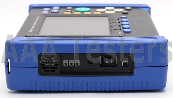
12 V DC from the AC ADAPTER 9458 or BATTERY PACK 9459 |
| Maximum rated power |
40 VA |
| Continuous operating time with battery |
Approximately 30 minutes (Battery pack 9459) |
| External dimensions |
Approximately 298W (11.73") × 215H (8.46") × 67D (2.64") mm (not including projections) |
| Mass |
Approximately 2.25 kg (79.4 oz.) (including Battery pack 9459) |
| Input specifications |
| Measurement line types |
Single-phase 2-wire, Single-phase 3-wire, Three-phase 3- wire (3P3W2M, 3P3W3M) or Three-phase 4-wire, plus one extra input channel
|
Input channels
Voltage
Current
|
4 channels (U1 to U4) (channel U4 can be switched between AC and DC)
4 channels (I1 to I4)
|
Input methods
|
Voltage between U1, U2, and U3 without inter-channel isolation
Voltage between U1 to U3 and U4 with inter-channel isolation
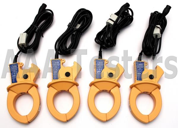
Current input by clamp-on sensor
|
Input resistance
Voltage
Current
|
4 MΩ ±10% (differential input)
200 kΩ ±10%
|
| Measurement method |
Simultaneous digital sampling of voltage and current PLL synchronization (automatically switches to fixed clock during dropouts, so sampling is never interrupted)
|
PLL synchronization channel source
|
Voltage at either U1, U2, or U3
|
| PLL synchronization frequency range |
42.5 to 69 Hz |
Sampling frequency:
For calculations (including DC measurement)
For harmonic and inter-harmonic analysis
For transient overvoltage (impulse)
|
256 points/cycle
256 points/8 cycles (for 400 Hz)
2048 points/10 cycles (for 50 Hz)
2048 points/12 cycles (for 60 Hz)
2048 points/80cycles (for 400 Hz)
2 MHz
|
A/D converter resolution
For calculations (including DC measurement)
For transient overvoltage (impulse)
|
16 bits
12 bits
|
Voltage measurement range
Channels 1 to 3
Channel 4
|
150.00, 300.00, 600.00 Vrms
60.000, 150.00, 300.00, 600.00 Vrms
±60.000, 600.00 V pk (DC measurement)
|
| Voltage crest factor |
3 or less |
Current measurement range
With Model 9694 sensor
With Model 9660 sensor
With Model 9661 sensor
With Model 9667 sensor
With Model 9669 sensor
|
5.0000, 50.000 Arms
50.000, 100.00 Arms
50.000, 500.00 Arms
50.000, 500.00 A or 500.00 A, 5.0000 kArms
100.00 A, 1.0000 kArms
|
Current crest factor
|
4 or less
|
| Measurement specifications |
RMS voltage
|
Measurement method
|
True RMS (calculated continuously every 10 or 12 cycles at 50 or 60 Hz respectively)
|
Range selection
|
Manual (channels 1 to 3 are set in the same operation)
|
Measurement accuracy
|
AC : ±0.2% rdg. ±0.1% f.s.
DC : ±0.3% rdg. ±0.4% f.s.
|
| RMS current |
Measurement method
|
True RMS (calculated continuously every 10 or 12 cycles at 50 or 60 Hz respectively)
|
Range selection
|
Manual (channels 1 to 3 are set in the same operation)
|
| Measurement accuracy |
±0.2% rdg. ±0.1% f.s. + clamp-on sensor accuracy |
Transient overvoltage (impulse)
|
Measurement method
|
2 MHz sampling
|
Measurement range
|
2000 Vpk |
Display items
|
4 ms waveform (2 ms before and after center peak)
|
| Period |
Period exceeding threshold (max. 4 ms) |
| Minimum detectable duration |
0.5 µs |
| Measurement accuracy |
±5.0% rdg. ±20 V (1000 V DC and 700 Vrms/100 kHz) |
Voltage swell (rise in RMS voltage)
|
Measurement method
|
True RMS (a single cycle is calculated by overlapping each half cycle) (The voltage between lines is measured for three phase 3-wire lines, and phase voltage is measured for three phase 4-wire lines.
|
Display items
|
Amplitude and duration of swell |
Measurement accuracy
|
Same as RMS voltage
|
Voltage dip (drop in RMS voltage)
|
Measurement method
|
True RMS (a single cycle is calculated by overlapping each half cycle) (The voltage between lines is measured for three phase 3-wire lines, and phase voltage is measured for three phase 4-wire lines.)
|
| Display items |
Amplitude and duration of dip
|
Measurement accuracy
|
Same as RMS voltage |
Instantaneous Interruption
|
| Measurement method |
Same as voltage dip |
Frequency
|
Measurement range
|
42.500 to 69.000 Hz |
Measurement source
|
Voltage (same as the PLL synchronization source) |
Measurement accuracy
|
±10 mHz (10 to 110% of range, with sine wave) |
Active power
|
Measurement method
|
Calculated continuously every 10 or 12 cycles at 50 or 60 Hz respectively
|
| Measurement accuracy |
±0.2% rdg. ±0.1% f.s. + clamp-on sensor accuracy |
| Reactive power |
| Measurement accuracy |
±1 dgt. from the calculation of each measurement value (±3 dgt. for the sum) |
| Power factor |
Measurement range
|
-1.000 (lead) to 0.000 to +1.000 (lag)
|
Measurement accuracy
|
±1 dgt. from the calculation of each measurement value (±3 dgt. for the sum)
|
Displacement power factor
|
Measurement method
|
Calculated from the phase difference between the fundamental waveforms of voltage and current
|
| Measurement range |
-1.000 (lead) to 0.000 to +1.000 (lag) |
Measurement accuracy
|
±0.5% rdg. ±0.2% f.s. ±1 dgt.(±3 dgt. for the sum)
|
| Voltage unbalance factor |
| Measurement method |
Calculation for three-phase 3-wire (3P3W3M) and three phase 4-wire fundamental waveforms of voltage |
| Current unbalance factor |
Measurement method
|
Calculation for three-phase 3-wire (3P3W3M) and three-phase 4-wire fundamental waveforms of current |
∆V10 flicker
|
Display items
|
∆V10, ∆V10 (average over one hour, fourth maximum over one hour, maximum over one hour, overall maximum (during the measurement period)), ∆U (deviation with respect to nominal voltage)
|
Standard voltage: Auto
|
Same operation as AGC for IEC flicker |
Measurement accuracy
|
±2% rdg |
IEC flicker (short period flicker Pst, long period flicker Plt)
|
| Measurement method |
Per IEC61000-4-15 Pst is measured for 10 minutes, and Plt is measured for 2 hours
|
Measurement accuracy
|
±5% rdg. or less of the limit value |
Harmonic voltage, current and power (including fundamental waveform components)
|
Analysis window
|
Rectangular
|
| Analysis orders |
1 to 50
|
Measurement accuracy
Voltage/current
Power
|
1st to 20th orders : ±0.5% rdg. ±0.2% f.s.
21st to 50th orders : ±1.0% rdg. ±0.3% f.s
1st to 20th orders : ±0.5% rdg. ±0.2% f.s.
21st to 30th orders : ±1.0% rdg. ±0.3% f.s.
31st to 40th orders : ±2.0% rdg. ±0.3% f.s.
41st to 50th orders : ±3.0% rdg. ±0.3% f.s
|
Inter-harmonic voltage and current
|
Analysis window
|
Rectangular
|
Analysis orders
|
0.5 to 49.5 |
Harmonic voltage/current phase difference (including fundamental waveform content)
|
Measurement method
|
Difference between voltage and current phase angle components |
Display items
|
Sum of all or multiple channels |
| Measurement accuracy |
1st to 3rd orders : ±2˚
4th to 50th orders : ±(0.02˚ × k+2˚), k = harmonic order
|
| Display specifications |
Display device
|
6.4" TFT color LCD (640 × 480 dots) |
| Text display |
English, German, French, Italian, Spanish, Chinese or Japanese |
| External interface specifications |
External control terminals
|
External event input and output
|
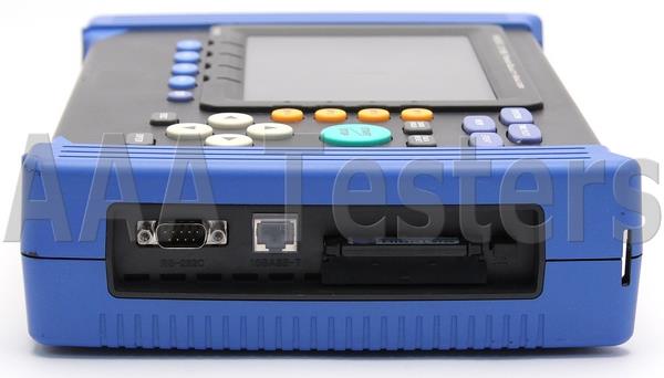
| PC card interface Slot |
Compliant with PCMCIA/JEIDA PC Card Standard, Type II slot × 1
|
Compatible cards
|
Flash ATA cards up to 528 MB
|
RS-232C interface
Standard
Destination device
Printer interval selections
|
EIA RS-232C-compliant (with 9-pin D-sub connector)
Printer or modem or GPS
OFF, 1, 5, 10, or 30 minutes, 1 or 2 hours
|
LAN interface
Communications protocol
|
Ethernet and TCP/IP (with 10BASE-T RJ-45 connector)
|
| Environment & safety specifications |
Operating environment
|
Indoors, up to a height of 2000 m (6562.2 ft) |
| Storage temperature & humidity |
-20 to 50˚C, max. 80% rh (non-condensating) |
Operating temperature and humidity
|
0 to 40˚C, max. 80% rh (non-condensating)
|
Maximum measurement terminal voltage
Voltage terminals
Current terminals
|
780 Vrms AC, 1103 V peak
1.7 Vrms AC, 2.4 V peak
|
Maximum in-phase voltage
|
600 Vrms AC (50/60 Hz, voltage input terminals) |
| Withstand voltage |
5.55 kVrms AC/1 min (50/60 Hz, 1 mA current sensitivity) Between voltage and clamp input terminals, between the voltage input terminal and 3196 casing, and between voltage input terminals (U1 to U3) and voltage input terminal (U4)
|
Enclosure protection
|
IP30 (per EN60529) |
Standards conformance
EMC
Safety
Voltage input unit |
EN61326 CLASS A, EN61000-3-2 and EN61000-3-3
EN61010
Contamination Level 2, Measurement Category III
|

















 We Ship World Wide!