Specification:
Model: KSA100
Output channel: 2.0 channels
Amplifier tube: MJ15024G * 8, MJ15025G * 8
Frequency response range: 20-20KHz
Voltage: AC32V-0-AC32V with rectifier bridge 0-AC12V
AC32V-0-AC32V with rectifier bridge 0-AC12V
Output power: Class A and Class B 350W * 2/42 Class A 100W * 2/40 50W * 2/82
Total harmonic distortion: ≤ 0.02%
Protection mechanism: Startup delay protection
Size: 121 * 271mm
Weight: 0.65KG+0.65KG
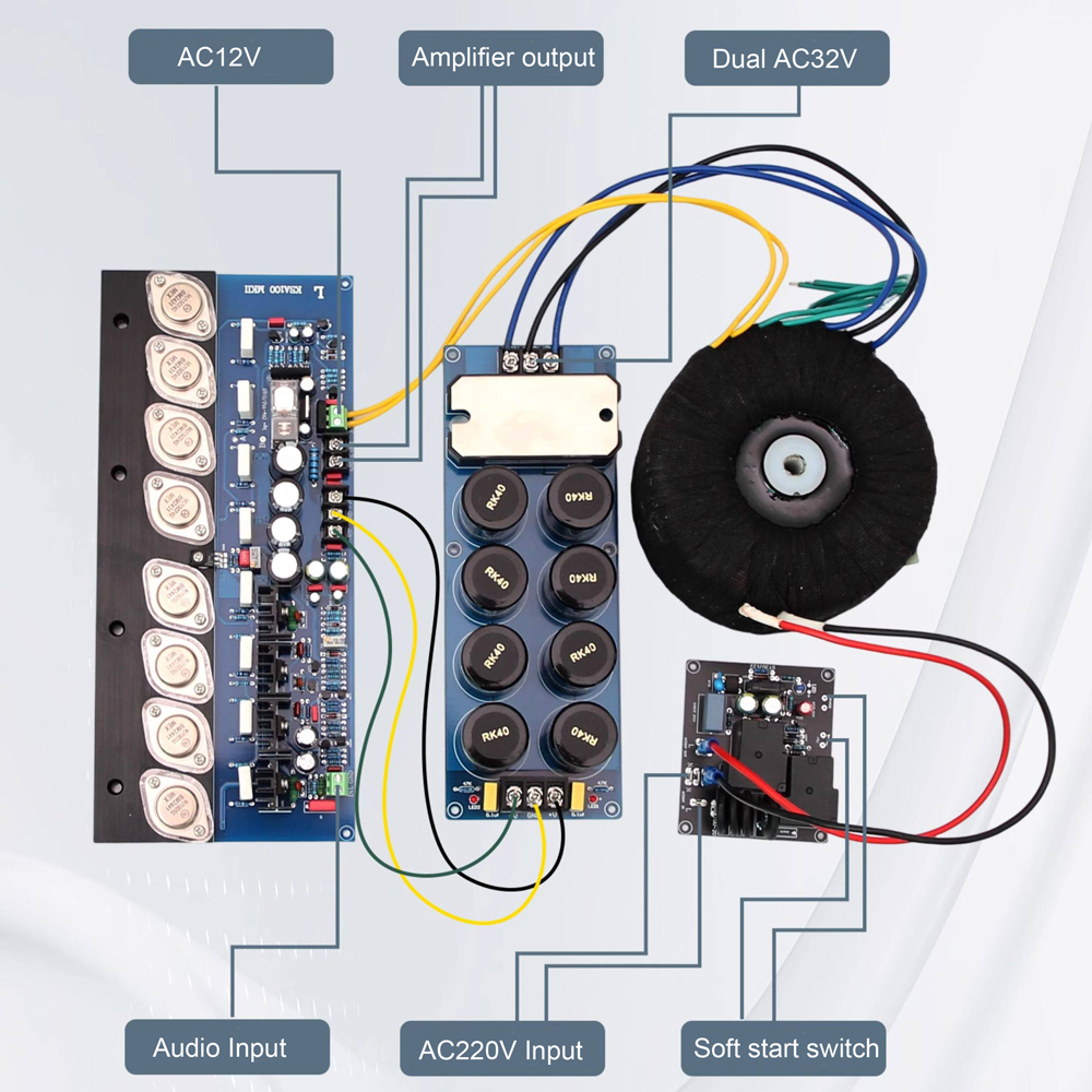
Wiring Instructions
As shown in the above figure, this is a complete installation wiring diagram for one channel. The 220V mains power first passes through the soft start control board to prevent excessive capacitor charging current during startup. Then the output of the soft start board is connected to a transformer, and the main voltage of the transformer is double 32V connected to a rectifier bridge. After rectification and filtering, it becomes a direct current of 45V and is output to the main power interface of the power amplifier board. The transformer is connected to the AC12V interface of the power amplifier board via a single 12V connection, providing power to the horn protection circuit. Finally, connect the audio input and amplifier output to complete the wiring
As shown in the above figure, this is a complete installation wiring diagram for one channel. The 220V mains power first passes through the soft start control board to prevent excessive capacitor charging current during startup. Then the output of the soft start board is connected to a transformer, and the main voltage of the transformer is double 32V connected to a rectifier bridge. After rectification and filtering, it becomes a direct current of 45V and is output to the main power interface of the power amplifier board. The transformer is connected to the AC12V interface of the power amplifier board via a single 12V connection, providing power to the horn protection circuit. Finally, connect the audio input and amplifier output to complete the wiring
Note:
1、 The power supply of the circuit board requires the use of a high-power transformer with a main voltage of 32V and a secondary voltage of 12V, followed by the addition of a rectification and filtering board before it can be connected to the KSA100 power amplifier board, and cannot be directly connected to the transformer. It is recommended to use a toroidal transformer with a main voltage power of over 400 watts, and the main voltage should not exceed 32V too much. A power of 10 watts with a secondary voltage of 12V is sufficient.
2、 The AC12V interface of the circuit board is used to supply power to the protection circuit and requires a separate 12V output from the transformer. It cannot be shared with other circuits.
3、 The line from the rectifier board to the power amplifier board cannot be connected incorrectly, and the positive and negative poles and ground wire must be connected correspondingly, because this is DC power. The recommended capacitance for rectification and filtering capacitors is 80000 microfarads.
4、 To ensure a high signal-to-noise ratio, it is recommended to connect the audio input ground to the chassis ground instead of using the power ground to connect the chassis.
5、 KSA100 is a Class A amplifier that must be installed on a large heat sink. The connection parts need to be coated with thermal conductive silicone grease to achieve rapid heat dissipation. It is recommended to use aluminum alloy heat sinks weighing more than 4 kilograms.
6、 The installation and debugging of KSA100 requires professional circuit knowledge. If you lack experience, please study and understand before starting.
Debugging steps
1、 After connecting all the wires to the power amplifier board, find a power cord with an incandescent bulb connected in series to the mains input live wire. Connect it to the soft start board to protect the power amplifier board from damage when the wrong wire is connected. LED lights cannot be used, and old-fashioned incandescent bulbs must be used.
2、 Adjust the VR2 adjustable resistor clockwise for a few more turns, adjust the static current to 0MV, and then turn on the power to power on the entire circuit board. When the power is first turned on, the previously connected light bulb will light up. This is to charge the capacitor, and the current passing through will make the light bulb light up. After a while, the light bulb will slowly dim, indicating that the capacitor is fully charged, and then you can hear the sound of the relay closing. If the light bulb stays very bright, it means there is a wiring error and all wiring needs to be checked for correctness.
3、 After the previous step, if there is no problem with normal power on, replace it with another power cord that does not have a connected light bulb, and then turn it on. Use the multimeter voltage MV gear to measure the voltage between two points of the output terminal on the circuit board, and then adjust the VR1 adjustable resistance to make the voltage OMV, which has been adjusted to 0MV in the factory. Then use the multimeter to measure the voltage between two points of AB, and adjust the VR2 adjustable resistance to make the voltage 22MV. At this time, the current of each tube is 100ma. The calculation formula is I=U/R, 22MV/0.22R=100ma. Before adjusting the static current, it is necessary to install a large radiator. After being powered on for a period of time, the overall temperature will rise, and the static current will also rise. Then, it will stabilize at a certain point. The voltage value at point AB after stabilization is about 35MV, and the static current is about 160mA.

On Mar 5, 2026 at 21:41:38 PST, seller added the following information: