
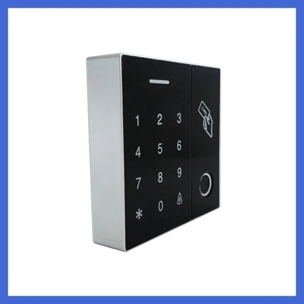
Techincal Parameters
- Operating Voltage:DC12V ;
- Stand-by current:≤30mA;
- Frequency:125KHz
- Card type:EM 4100/4102 125Khz ID CARD
- Reading distance:3~9cm;
- User storage:2000;
- Fingerprint user:230
- Ambient temperature:-35℃~60℃;
- Electric lock output:≤2A;
- Alarm Output:≤1A;
- Opening time:0~99s adjustable (factory default is 5 seconds);
- Size:86*86*22mm ;
PIN description
NO | Line | Mark | Color | Function |
P5 | ||||
P5
| 1 | WG34 | gray | WG34 |
2 | GND | black | GND | |
3 | OPEN | yellow | EXIT Button GND | |
4 | B_B | Pink | Bell | |
5 | B_A | brown | Bell | |
6 | 12V | red | DC12V-24VDC | |
P1 | ||||
P1 | 1 | D0 | green | D0 |
2 | D1 | white | D1 | |
3 | COM | purple | COM | |
4 | NO | blue | NO | |
5 | NC | Orange | NC | |
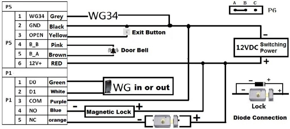
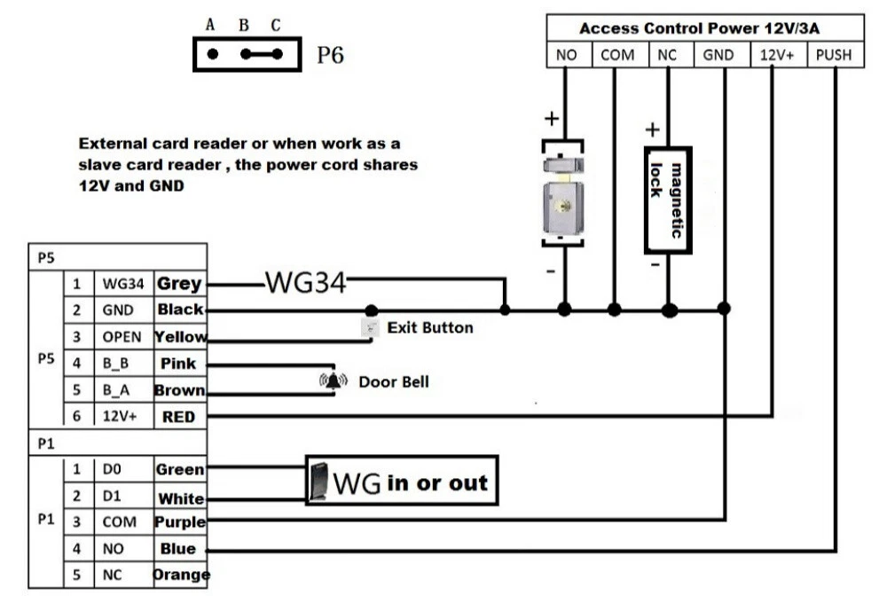
Wiring diagram
Switching power supply wiring diagram (Note: The relay signal setting motherboard P6 jumper end A and B feet are connected with jumper cap)
Access control special power wiring diagram (Note: The level output settings of the mainboard P6 jumper end B and C are connected with a jumper cap)
Package:
- 1 x standalone access control
- 1 x 5pin cable
- 1 x 6pin cable
