Introduce
Mega2560-CORE is a small, complete and breadboard-friendly board base on the ATMega2560。Its design is based on the Arduino Mega2560,so we can use it as a Arduino Mega2560 development board. In a different place, it lacks only a 6-foot download port and a reset switch. Reducing the hardware circuit that can we reduce the power consumption and the cost. Mega2560-CORE has a matching download line and the other one end of the download cable is a USB interface, so it is very convenient for use.
Features
● Microcontroller ATmega2560
● Operating Voltage (logic level) 3.3V or 5 V
● Digital I/O Pins 54 (of which 15 provide PWM output)
● Analog Input Pins 16
● DC Current per I/O Pin 40 mA
● Flash Memory 256KB
● SRAM 8 KB
● EEPROM 4KB (ATmega2560)
● Clock Speed 16 MHz
● Low power consumption, low cost
Pin Number Figure Schematic
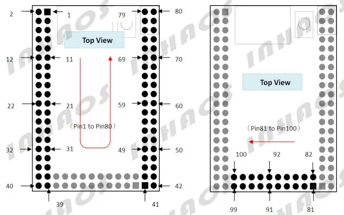
Pin Description Table
|
Pin |
Function /MCU |
Arduino Mega2560 |
|
Pin |
Function /MCU |
Arduino Mega2560 |
|
Pin |
Function /MCU |
Arduino Mega2560 |
|
1 |
VCC |
|
40 |
GND |
|
79 |
PB3 |
D50 |
||
|
2 |
VCC |
|
41 |
AGND |
|
80 |
VCC |
|
||
|
3 |
PG5 |
D4 |
42 |
AGND |
|
81 |
VCC |
|
||
|
4 |
PE0 |
RXD |
43 |
ADC0 |
A0/D54 |
82 |
VCC |
|
||
|
5 |
PE1 |
TXD |
44 |
VREF |
|
83 |
PC7 |
D30 |
||
|
6 |
PE3 |
PWM/D5 |
45 |
ADC2 |
A2/D56 |
84 |
PC6 |
D31 |
||
|
7 |
PE4 |
PWM/D2 |
46 |
ADC1 |
A1/D55 |
85 |
PC5 |
D32 |
||
|
8 |
PE5 |
PWM/D3 |
47 |
ADC4 |
A4/D58 |
86 |
PC4 |
D33 |
||
|
9 |
PE6 |
D74 |
48 |
ADC3 |
A3/D57 |
87 |
PC3 |
D34 |
||
|
10 |
PE7 |
D75 |
49 |
ADC6 |
A6/D60 |
88 |
PC2 |
D35 |
||
|
11 |
TXD3 |
D14 |
50 |
ADC5 |
A5/D59 |
89 |
PC1 |
D36 |
||
|
12 |
RXD3 |
D15 |
51 |
ADC8 |
A8/D62 |
90 |
PC0 |
D37 |
||
|
13 |
TXD2 |
D16 |
52 |
ADC7 |
A7/D61 |
91 |
PG1 |
D40 |
||
|
14 |
RXD2 |
D17 |
53 |
ADC10 |
A10/D64 |
92 |
PG0 |
D41 |
||
|
15 |
TXD1 |
D18 |
54 |
ADC9 |
A9/D63 |
93 |
PD7 |
D38 |
||
|
16 |
RXD1 |
D19 |
55 |
ADC12 |
A12/D66 |
94 |
PD6 |
D72 |
||
|
17 |
SDA |
D20 |
56 |
ADC11 |
A11/D65 |
95 |
PD5 |
D71 |
||
|
18 |
SCL |
D21 |
57 |
ADC14 |
A14/D68 |
96 |
PD4 |
D70 |
||
|
19 |
PH2 |
D78 |
58 |
ADC13 |
A13/D67 |
97 |
PG4 |
D77 |
||
|
20 |
PH3 |
PWM/D6 |
59 |
PJ2 |
D80 |
98 |
reserv |
|
||
|
21 |
PH4 |
PWM/D7 |
60 |
ADC15 |
A15/D69 |
99 |
GND |
|
||
|
22 |
PH5 |
PWM/D8 |
61 |
PJ4 |
D82 |
100 |
GND |
|
||
|
23 |
PH6 |
PWM/D9 |
62 |
PJ3 |
D81 |
|
|
|
||
|
24 |
PB0 |
53 |
63 |
PJ6 |
D84 |
|
|
|
||
|
25 |
PB4 |
PWM/D10 |
64 |
PJ5 |
D83 |
|
|
|
||
|
26 |
PB5 |
PWM/D11 |
65 |
PA7 |
D29 |
|
|
|
||
|
27 |
PB6 |
PWM/D12 |
66 |
PG2 |
D39 |
|
|
|
||
|
28 |
PB7 |
PWM/D13 |
67 |
PA5 |
D27 |
|
|
|
||
|
29 |
PL0 |
D49 |
68 |
PA6 |
D28 |
|
|
|
||
|
30 |
PL1 |
D48 |
69 |
PA3 |
D25 |
|
|
|
||
|
31 |
PL2 |
D47 |
70 |
PA4 |
D26 |
|
|
|
||
|
32 |
PL3 |
PWM/D46 |
71 |
PA1 |
D23 |
|
|
|
||
|
33 |
PL4 |
PWM/D45 |
72 |
PA2 |
D24 |
|
|
|
||
|
34 |
PL5 |
PWM/D44 |
73 |
PJ7 |
D85 |
|
|
|
||
|
35 |
PL6 |
43 |
74 |
PA0 |
D22 |
|
|
|
||
|
36 |
PL7 |
42 |
75 |
RESET |
|
|
|
|
||
|
37 |
PH7 |
D79 |
76 |
GND |
|
|
|
|
||
|
38 |
PG3 |
D76 |
77 |
PB1 |
D52 |
|
|
|
||
|
39 |
GND |
|
78 |
PB2 |
D51 |
|
|
|
Indicator Description
Programming Connection
There are two way to download and they are as follows:
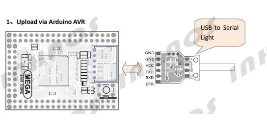
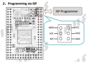
1 x Mini 2560
1 x USB cable