Features:
1.LCD can display input / output voltage, output current / output power / output capacity / output time;
2 .CNC adjustment, accurate and fast, can reduce the voltage, the output voltage can be adjusted at will from 0-50.00v, the limit current 0-A can be adjusted at will;
3. The outlet end is poured back without burning;
4. The module can be set to open / close by default;
5. There are various software protection mechanisms available and the protection threshold is adjustable. When the operating parameters of the module exceed the protection threshold, the output will automatically close.
6. Using synchronous rectification technology, the conversion efficiency is high: The efficiency is more than 90%.
7.Increase the heat sink, install the fan, strengthen the heat dissipation.

Inputvoltagerange:6-55.00V Inputvoltageresolution:0.01V
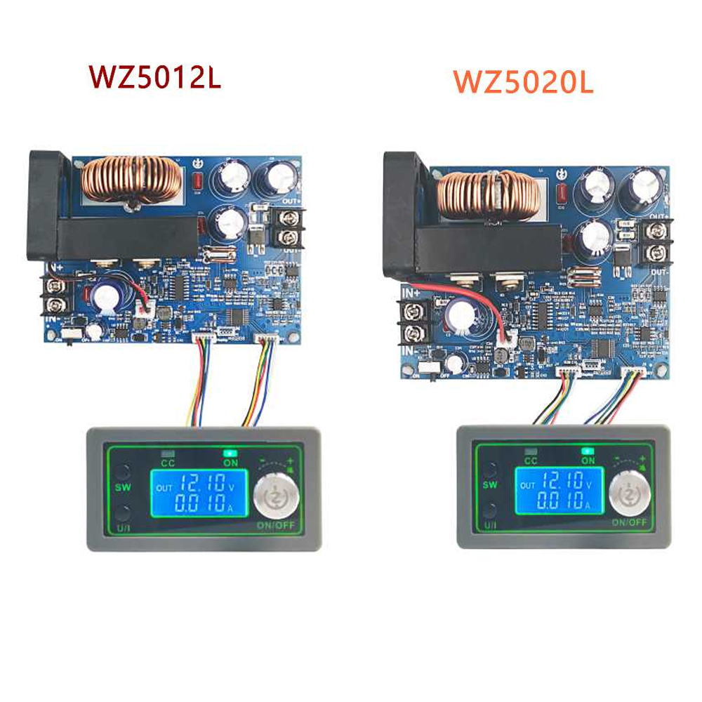
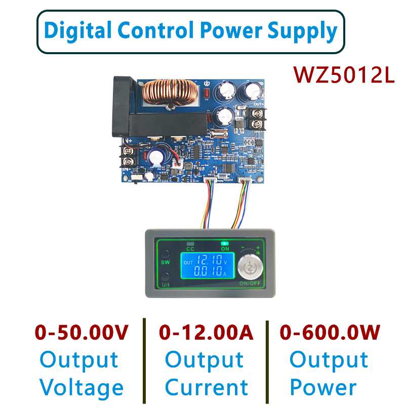
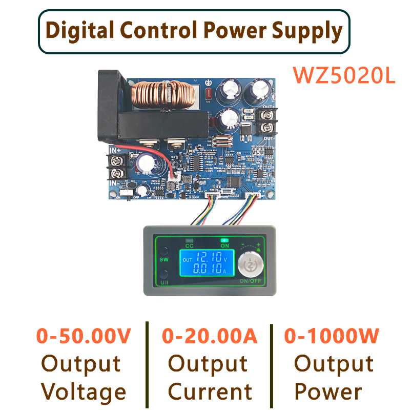
Outputvoltagerange:0-50.00V Outputvoltageresolution:0.01V
Outputcurrentrange:0-20.00A Outputcurrentresolution:0.01A
Outputpowerrange:0-1000W Inputvoltageaccuracy:±(1%+5)
Outputvoltageaccuracy:±(0.3%+5) Outputcurrentaccuracy:±(0.5%+5)
Typicalvalueofoutputripple:150mV Normaloperatingtemperaturerange:Peakvalue-10℃~40℃
Capacitymeasurementrange:0-999.9AH Statisticalerrorofcapacityenergy:±2%
Statisticaltimerange:0-100hour Depressurizationmode:differential pressure>0.05%+1V
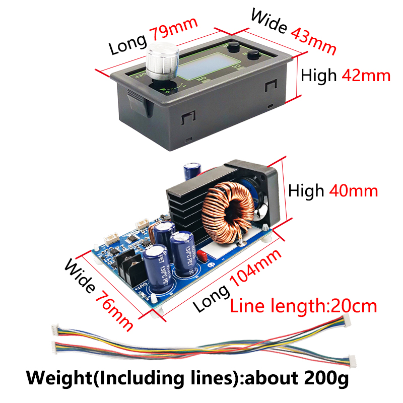
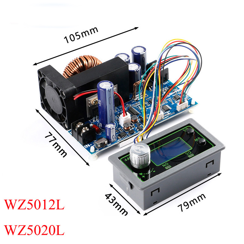
Theweightofnude:200g Productsize:panel79X43X42mm
Includingpacking:242g mainboard:106x76x40mm
Protectionmechanism:
Inputundervoltageprotection(5.8-50vadjustable,default5.8v)
Outputovervoltageprotection(0-51.00vadjustable,default
51V)
Outputover-currentprotection(0-20.10aadjustable,default
20.10a)
Timeoutprotection(0-100hadjustable,offbydefault)
default)

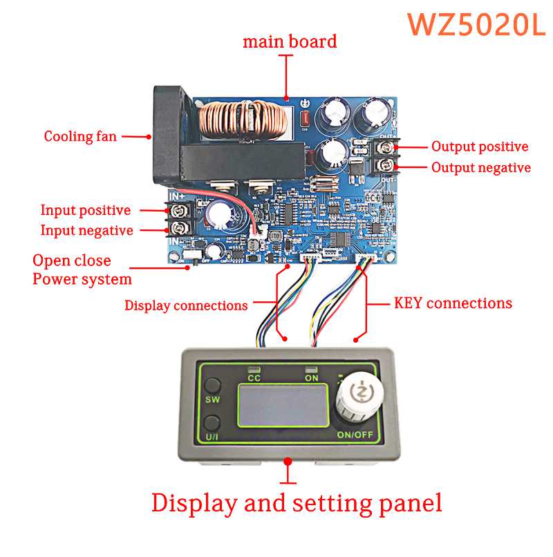
Key description:


Note:after the product triggers theprotection mechanism,the output will automatically turn off,the LCD will display the
protection code,and press any key to exit the protection interface.
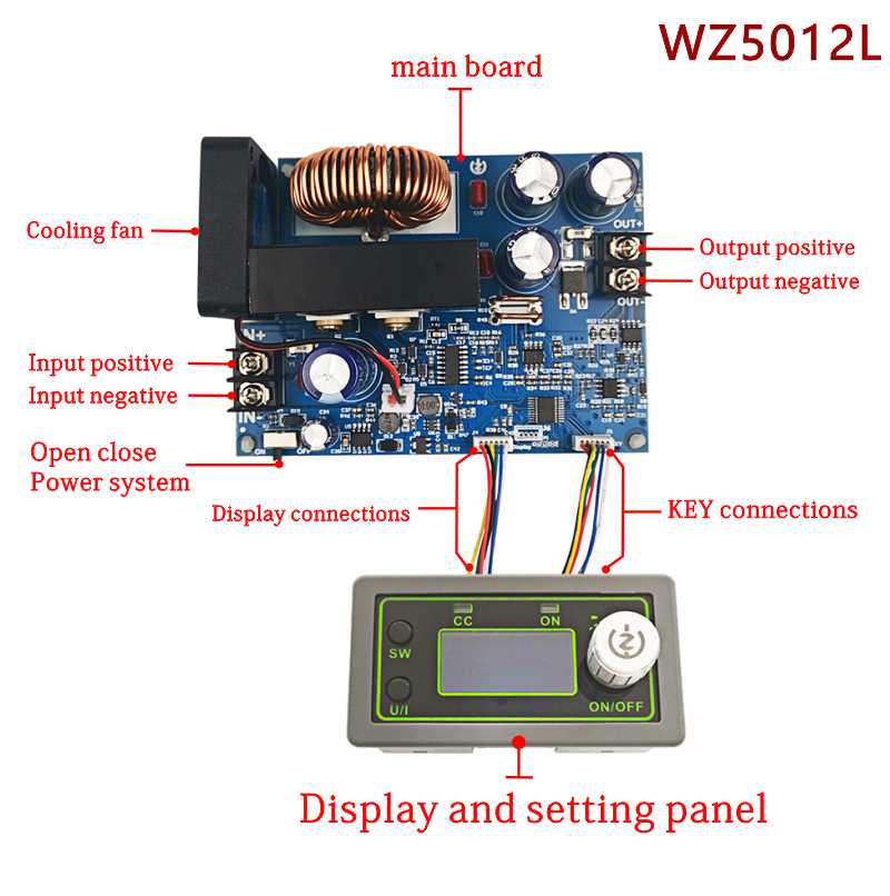
Interfacedescription:

Method of use:
1. Switch display parameters -- in the normal interface, press SW to switch the display below the display screen, and switch the display content between current A power W capacity Ah time h.Long press SW button to switch the uplink display on the display screen and switch the display content between input voltage IN output voltage OUT.
2. Set output voltage -- press U/I button in the normal interface to enter the interface of setting voltage constant current.It can be seen that a certain digit of the output voltage value is flashing. Rotate the encoder left and right to adjust the major and minor.Short press the rotary encoder to choose which bit of output voltage to set.After setting, press U/I button 2 times to return to the normal interface.Or automatically return to the normal interface after stopping operation for 10s.
3. Set constant current value (that is, the maximum current value allowed to output by the module) -- press U/I button in the normal interface to enter the setting voltage constant current interface.Then press U/I button and switch to setting constant current value. You can see a bit of the setting constant current value flashing. Rotate the rotary encoder left and right to adjust the major and minor.Short press the rotary encoder to choose which bit to set the constant current value.After setting, press U/I to exit the setting voltage constant current interface and return to the normal interface.Or automatically return to the normal interface after stopping operation for 10s.
4. Set the default on/off state of module power-on -- long press U/I in the normal interface to enter the parameter setting interface.You can see that it shows "OPEN OFF" or "OPEN ON". "OPEN OFF" means the output is turned OFF by default when power is ON, and "OPEN ON" means the output is turned ON by default when power is ON.Long press rotate encoder to switch two states.After setting, long press U/I to return to the normal interface.
5. Setting of protection parameters on state and threshold -- long press U/I to enter the parameter setting interface in the normal interface.Press SW until the protection you want appears.LUP -- undervoltage protection threshold;OUP -- overvoltage protection threshold;OCP -- overcurrent protection threshold;OAP -- ultra-capacity protection threshold;OHP timeout protection threshold.Short press rotate encoder to select which bit you want to set the protection parameter.Long press the rotary encoder to set the protection parameters on or off (only timeout protection and supercapacity protection can be set to turn on/off, and other protection parameters are turned on by default.).Rotate the encoder left and right to make the parameters bigger and smaller.After setting, long press U/I to return to the normal interface.
6. Calibration voltage and current -- press U/I button to enter the parameter setting interface under normal interface. Press SW key for a short time until the interface with zero appears, with zero + out + a symbol. Press and hold the rotary encoder to complete zero calibration. Short press SW button until a parameter interface with CAL appears.The calibration input voltage interface with the symbol CAL+IN+V;The calibration output voltage interface with the symbol CAL+OUT+V;The calibration output current interface with the symbol CAL+OUT+A.Rotate the encoder left and right to adjust the size of parameters.After the adjustment is completed, long press the rotary encoder to confirm the adjustment is completed, and the parameter value is no longer flashing.Long press U/I to return to the normal interface.
Note: in order to ensure the accuracy of calibration, calibration voltage -- above 12V can only be started;Calibration current - start calibration only when the current is above 1A.
Packing form:

1. The module input positive in + and negative in - must not be reversed, and the module input in - must not be short circuited with the output out -, otherwise the module may be burnt out.
3. This module is a step-down module, the input voltage should be higher than the output voltage, and a certain margin should be reserved. For full load output, the input voltage should be 55v.
4. High power use of this module, serious heating, high temperature, be careful of scald! Please pay attention to ventilation and heat dissipation when using high power for a long time!