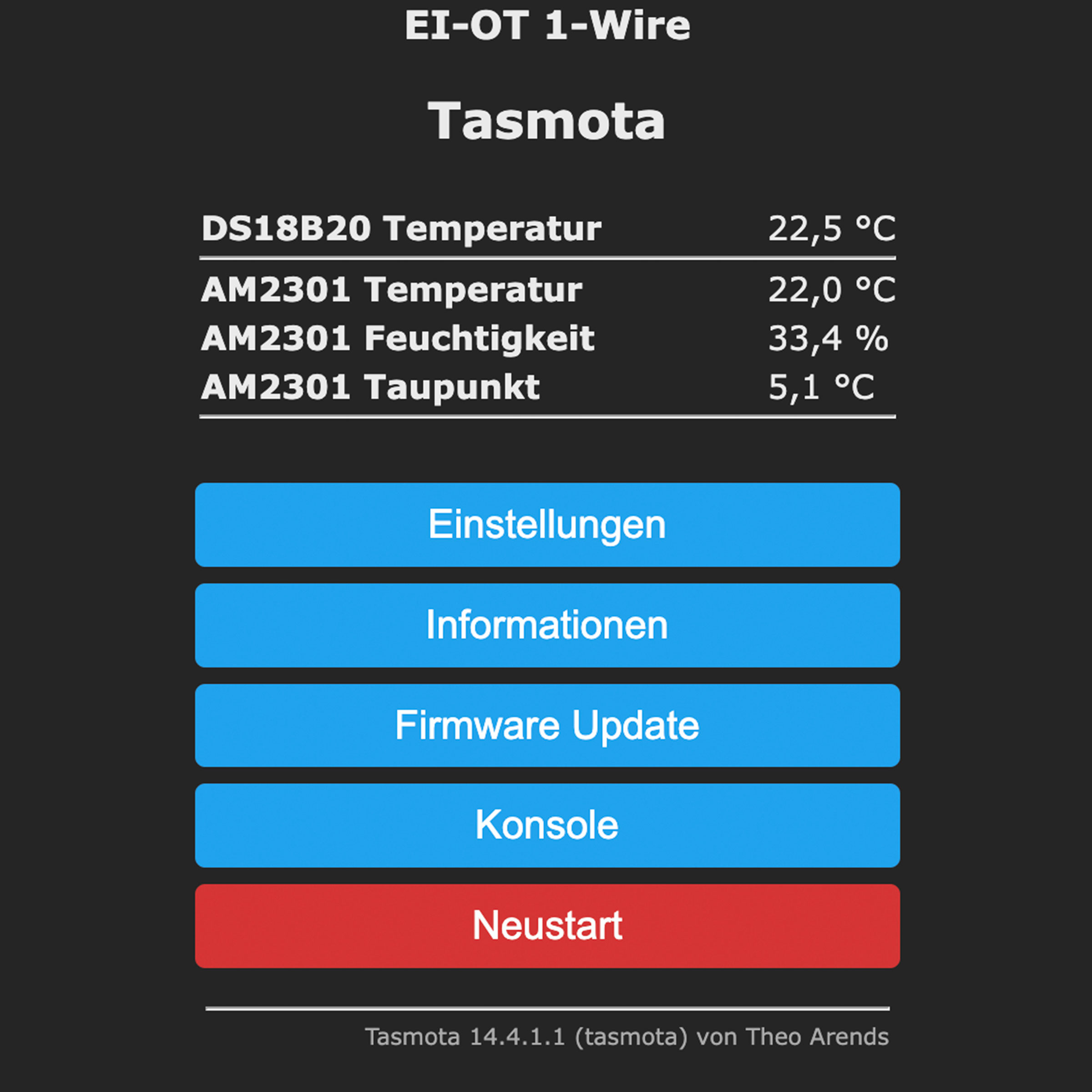
EI-OT Tasmota 1-wire Bausatz

Tasmota EI-OT DS18B20 AM2301 DHT11 DHT22 ESP8266 5V Temperatur Luftfeuchte WLan Konverter Bausatz

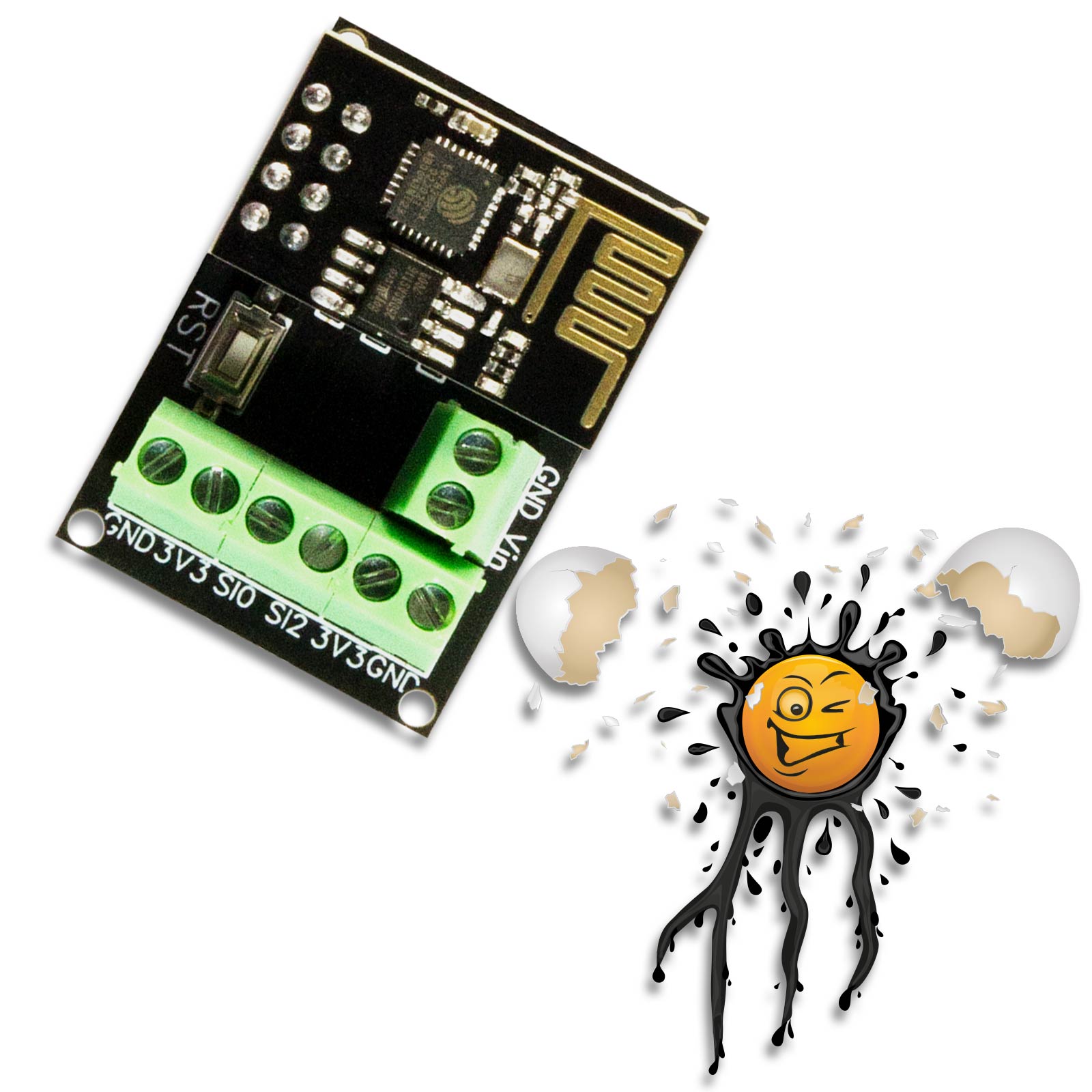
ESP8266 EI-OT WiFi Smart Home 1-wire Sensor Module © ei-ot ®
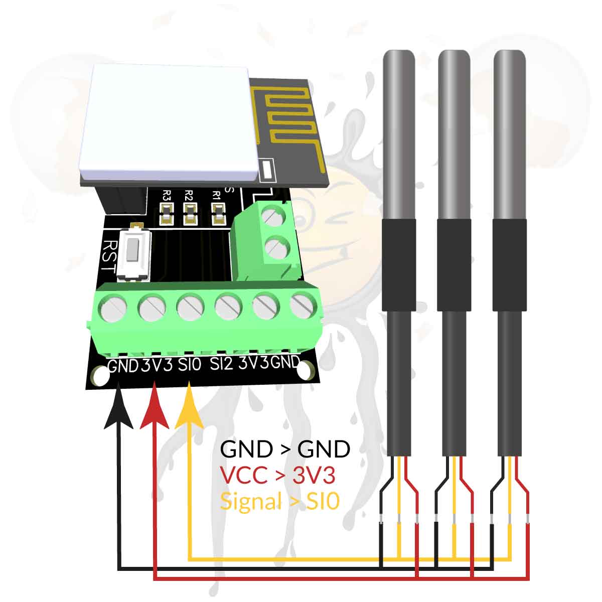
ESP8266 EI-OT WiFi Smart Home 1-wire Module DS18B20 Sensor connection © ei-ot ®
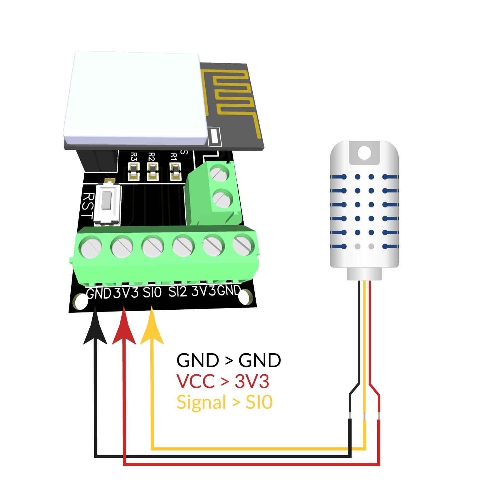
ESP8266 EI-OT WiFi Smart Home 1-wire Module DS18B20 Sensor connection © ei-ot ®


Das EI-OT 1-Wire Modul ist ideal für den Einsatz in Kombination mit 1-Wire oder I2C Sensoren bzw. Modulen.

Das 1-Wire Modul basiert auf dem AI Thinker ESP8266 ESP-01 mit 8Mbit SPI Flash Speicher und erlaubt eine einfache Integration in lokale / private Heimnetzwerke.

Das der ESP-01 des EI-OT 1-wire Modul ist bereits mit der Tasmota Firmware geflasht und erlaubt die einfache Einbindung von folgenden 1-Wire Sensoren

  • DS18B20
  • DHT11
  • AM2301
  • DHT22
  • usw.

  • Der jeweilige Sensor wird mittels Schraubklemme mit dem EI-OT ESP8266 1-wire Modul verbunden
    GND = Sensor schwarzes Kabel
    3V3 = Sensor rotes Kabel
    SI0 oder SI2 = Sensor gelbes Kabel

    Das EI-OT ESP8266 1-wire Modul unterstützt bis zu 8 Stück DS18B20 am 1-wire Bus, weitere DS18B20 Sensoren bieten wir hier an.

    EI-OT 1-Wire Modul
    des EI-OT 1-Wire Modul verfügt über grundlegende Komponenten wie
    • 1 Stück AMS1117 3,3V Spannungskonverter sowie
    • 4 Stück Kondensatoren zur Glättung der Versorgungspannung
    • 2 Stück 4,7K PullUp Widerstände für den 1-Wire Signaleingang, bzw. für I2C SDA und SCL
    • Reset Taster
    • 1 Stück Stecksockel 4-polig 2-reihig für den ESP-01
    • KF350 Schraubanschlüsse für
      • 2 Stück 1-Wire Anschlüsse 3-polig, jeweils Signal, 3,3V+, GND
      • 1 Stück VCC Spannungsversorgung 5V Gleichspannung
     

    Die 2 1-Wire Kanäle sind auf GPIO0 und GPIO2 des ESP8266 ESP-01 gelegt und können mittels dem integrierten Tasmota Template aktiviert werden.


    Die Tasmota Firmware des EI-OT 1-Wire Modul hat Treiber für folgende Sensoren und Module bereits integriert

    1-Wire Sensoren und Module:

      • DS18B20 Temperatursensor
      • DHT11 zur Bestimmung von Temperatur,  Luftfeuchtigkeit, sowie Taupunkt
      • AM2301 / DHT22 auch zur Bestimmung von Temperatur,  Luftfeuchtigkeit, sowie Taupunkt jedoch mit einer höheren Genauigkeit


    Inbetriebnahme
    Die Inbetriebnahme ist denkbar einfach und eignet sich selbst für Smart Home Einsteiger. Der jeweilige Sensor muss lediglich an einem der 2 1-wire Kanäle wie folgt angeschlossen werden
    • rot VCC 3,0V+ bis 5,5V+
    • schwarz GND 3,0V- bis 5V-
    • gelb 1-Wire Signal GPIO der MCU
     

    Ideal für Smart Home Einsteiger, für eine Inbetriebnahme in Minuten, die DS18B20 Messsonde in Kombination mit unserem EI-OT 1-Wire Modul


    The EI-OT 1-Wire module is ideal for use in combination with 1-Wire or I2C sensors or modules.

    The 1-Wire module is based on the AI ​​Thinker ESP8266 ESP-01 with 8Mbit SPI flash memory and allows easy integration into local / private home networks.

    The ESP-01 of the EI-OT 1-wire module is already flashed with the Tasmota firmware and allows the following 1-wire sensors to be easily integrated

  • DS18B20
  • DHT11
  • AM2301
  • DHT22
  • etc.

  • The Sensor is connected thru Screw Connector to EI-OT ESP8266 1-wire Modul
    GND = Sensor black wire
    3V3 = Sensor red wire
    SI0 oder SI2 = Sensor yellow wire

    EI-OT ESP8266 1-wire Module supports up to 8pcs. DS18B20 on 1-wire Bus, additional DS18B20 Sensors you can find here.

    EI-OT 1-wire Module
    of the EI-OT 1-Wire Module Kit comes assembled  with all required components such as
    • 1 pcs. AMS1117 3.3V Voltage LDO Converter
    • 4  pcs. Capacitors
    • 2 pcs. 4,7K PullUp Resistors for 1-Wire Signal or  I2C SDA and SCL
    • Reset Key
    • 1 pcs. female Pin Socket 4-pole 2-rows for the ESP-01
    • KF350 Screw Connector
      • 2 pcs. 3-pole connector for 1-wire bus each with Signal, 3.3V+ and GND
      • 1 pcs. 2-pole connector for power supply 5V DC
     

    The 2 1-Wire channels or 1 I2C channel (SDA and SCL) are connected to GPIO0 and GPIO2 of the ESP8266 ESP-01. The required GPIO function could be activated thru integrated Tasmota Template.


    The Tasmota Firmware of the EI-OT 1-Wire I2C Module comes with drivers for Sensors and Modules follows

    1-Wire Sensors and Modules:

      • DS18B20 Temperature Sensor
      • DHT11 Temperature and  Humidity Sensor
      • AM2301 / DHT22 Temperature and  Humidity Sensor


    Installation
    Installation is extremely easy and is suitable even for smart home beginners. The respective sensor simply needs to be connected to one of the 2 1-wire channels as follows
    • VCC red wire to +3.0V up to +5.5V
    • GND black wire to -3.0V- up to -5.5V
    • Signal yellow 1-Wire Signal GPIO of MCU
       

    Perfect for Smart Home Beginner, Set Up in Minutes, DS18B20 Temperature Sensor in Combination with our EI-OT 1-Wire Module


    EI-OT 1-Wire Modul Features
    VCC Spannungsversorgung DC 5 Volt VCC  / Input Voltage DC 5 Volt
    Schnittstellen 2 x 1-Wire Kanal oder 1 x I2C Kanal Interfaces 2 x 1-Wire Channel or 1 x I2C Channel
    Protokolle HTTP, REST, MQTT, Domoticz, Home Assistant Protocols HTTP, REST, MQTT, Domoticz, Home Assistant
    typische Anwendung Betrieb von 1-Wire Sensoren sowie I2C Sensoren zur Einbindung in lokale WLan Netzwerke typical Application  Integration of 1-Wire or I2C Sensors in local WiFi Networks
    Leistung Strom Power Current
    AMS1117  Ausgangsstrom 1,6A (typ.) / 1,8A (max.) AMS1117 Output Current 1,6A (typ.) / 1,8A (max.)
    Stromverbrauch (ohne externe Module oder Sensoren) 80mA (durchschnittlich)

    270mA (max.)

    23mA (Modem Sleep)

    5mA (Light Sleep)

    <3mA (Deep Sleep)

    Current Consumption (w/o external Sensors or Modules) 80mA (average)

    270mA (max.)

    23mA (Modem Sleep)

    5mA (Light Sleep)

    <3mA (Deep Sleep)

    WLan 802.11 WiFi 802.11
    Frequenzbereich 2412 – 2884 Mhz. Frequency Range 2412 – 2884 Mhz.
    Sendeleistung 802.11b: 16±2 dBm (@11Mbps)
    802.11g: 14±2 dBm (@54Mbps)
    802.11n: 13±2 dBm (@HT20, MCS7)
    Transmit Power 802.11b: 16±2 dBm (@11Mbps)
    802.11g: 14±2 dBm (@54Mbps)
    802.11n: 13±2 dBm (@HT20, MCS7
    Empfangs – Empfindlichkeit CCK, 1 Mbps : -90dBm
    CCK, 11 Mbps: -85dBm
    6 Mbps (1/2 BPSK): -88dBm
    54 Mbps (3/4 64-QAM): -70dBm
    HT20, MCS7 (65 Mbps, 72.2 Mbps): -67dBm
    Receiving Sensitivity CCK, 1 Mbps : -90dBm
    CCK, 11 Mbps: -85dBm
    6 Mbps (1/2 BPSK): -88dBm
    54 Mbps (3/4 64-QAM): -70dBm
    HT20, MCS7 (65 Mbps, 72.2 Mbps): -67dBm
    Sicherheit WEP/WPA-PSK/WPA2-PSK Security WEP/WPA-PSK/WPA2-PSK
    Antenne integrierte PCB Antenne 2 dBi Antenna integrated PCB Antenna
    IPv4 Unterstützung DHCP und statisch IPv4 Support DHCP and static
    Anschlüsse Connections
    P1 Schraubklemme 2-polig Spannungsausgang für Sensor 2 (GND / 3,3V) P1 Screw Connector 2-pole Sensor 2 Vout (GND / 3.3V)
    P2 Schraubklemme 2-polig Signaleingang (I2C SDA oder SCL)
    1-Wire SI2 GPIO2 ESP8266
    1-Wire SI0 GPIO0 ESP8266
    P2 Screw Connector 2-pole Signalinput (I2C SDA or SCL)
    1-Wire SI2 GPIO2 ESP8266
    1-Wire SI0 GPIO0 ESP8266
    P3 Schraubklemme 2-polig Spannungsausgang für Sensor 0 (3,3V / GND) P3 Screw Connector 2-pole Sensor 0 Vout (3.3V / GND)
    P4 Schraubklemme 2-polig Spannungsversorgung (Vin / GND) P4 Screw Connector 2-pole Power Supply (Vin / GND)
    Tasmota Firmware Tasmota Firmware
     Konfiguration  grafische Benutzeroberfläche über Browser http://192.168.4.1 Configuration   over Webinterface thru Browser http://192.168.4.1
    unterstützte Schnittstellen UART (Pins nicht ausgeführt)
    GPIO
    I2C
    1-Wire
    supported Interface UART (no Pins)
    GPIO
    I2C
    1-Wire
    integrierte 1-Wire Treiber integrated 1-Wire Driver
    DS18B20, DHT11, AM2301, DHT22 DS18B20, DHT11, AM2301, DHT22
    integrierte I2C Treiber integrated I2C Driver
    INA219, INA226, BH1750, TSL2561, SHT30, HTU-21, BMP085, BMP180, BMP280, BME280, BME680,  SGP30, VL53L0X ToF, LM75AD, GY-521 / MPU-6050, AHT10, AHT15, AHT20, DHT12, MCP9808 INA219, INA226, BH1750, TSL2561, SHT30, HTU-21, BMP085, BMP180, BMP280, BME280, BME680,  SGP30, VL53L0X ToF, LM75AD, GY-521 / MPU-6050, AHT10, AHT15, AHT20, DHT12, MCP9808

    DS18B20 Smart Home Temperatursensor Features
    VCC Spannungsversorgung 3,0 – 5,5 Volt VCC  / Input Voltage DC 3.0 – 5.5 Volt
    Schnittstellen 1-Wire Bus, unterstützt bis zu 8 DS18B20 Sensoren an einem 1-Wire Bus (je nach MCU / Bibliothek) Interfaces 1-Wire Bus, supports up to 8 DS18B20 Sensors on one 1-Wire Bus (based on MCU and Library)
    Auflösung 9-12 bit Resolution 9-12 bit
    typische Anwendung Smart Home Temperaturmessung typical Application  Smart Home Temperature Measurement
    Messbereich -55°C bis +125°C Measurement Range -55°C to +125°C  (-67°F to +257°F)
    Messtoleranz bei -10°C bis +85°C ±0.5°C  Accuracy from -10°C to +85°C ±0.5°C 
    Messtoleranz bei -30°C bis +100°C ±1°C  Accuracy from -30°C to +100°C ±1°C 
    Messtoleranz bei -55°C bis +125°C ±2°C  Accuracy from -55°C to +125°C ±2°C 
    Leistung Strom Power Current
    Stromverbrauch 5V 1mA Current Consumption 5V 1mA
    Stromverbrauch 3,3V 1,6mA Current Consumption 3.3V 1.6mA

    AM2301 Smart Home Temperature Humidity Sensor Features
    VCC Spannungsversorgung 3,3 - 5,2 Volt VCC  / Input Voltage DC 3.3 - 5.2 Volt
    Schnittstellen 1-Wire Bus Interfaces 1-Wire Bus
    Auflösung 8 bit (Luftfeuchtigkeit)
    16 bit (Temperatur)
    Resolution 8 bit (Humidity)
    16 bit (Temperature)
    typische Anwendung Smart Home Temperatur- und Luftfeuchtigkeits- Messung typical Application  Smart Home Temperature and Humidity Measurement
    Temperatur Messbereich -40°C bis +80°C Temperature Measurement Range -40°C to +80°C
    Luftfeuchtigkeit Messbereich 0% bis 100% Humidity Measurement Range 0% bis 100%
    Messtoleranz bei 25°C ±0.3°C (typ.)
    ±3% (typ.)
    Accuracy @ 25°C ±0.3°C (typ.)
    ±3% (typ.)
    Messbereich Auflösung 0,1°C  Temperatur
    0,1% Luftfeuchtigkeit
    Measurement Resolution 0.1°C  Temperature
    0.1% Humidity
    Leistung Strom Power Current
    Stromverbrauch 5V 15 µA (standby)
    500 µA (Messung)
    300 µA (durchschnittlich)
    Current Consumption 5V 15 µA (standby)
    500 µA (measurement)
    300 µA (averrage)
    Stromverbrauch 3,3V 10µA (standby)
    500 µA (Messung)
    300 µA (durchschnittlich)
    Current Consumption 3.3V 15µA (standby)
    500 µA (measurement)
    300 µA (averrage)
    EI-OT Modul AP / Access Point SSID
    Tasmota WLan Konfiguration

    Die Tasmota Firmware erlaubt eine einfache WLan Konfiguration mittels Webinterface. An dieser Stelle sei erwähnt, die Tasmota Firmware unterstützt den SoftAP Modus (Access Point) lediglich zur WLan Konfiguration. Sobald das jeweilige Modul als Client in einem bestehenden Netzwerk eingebunden wurde, wird der SoftAP Modus nicht mehr unterstützt.

    Tasmota Client Anbindung mittels Webinterface

    Nachdem das jeweilige Modul mit Spannung versorgt wurde startet das Modul im SoftAP Modus. Innerhalb der Netzwerkumgebung eines

  • Computers
  • Mobiltelefon
  • Tablet
  • erscheint nun ein neuer Tasmota SoftAP / Access Point. Die WLan Konfiguration mittels dem Tasmota Webinterface erfolgt mittels 5 einfachen Schritten:

    1. Stelle eine WLan Verbindung über Systemeinstellungen / Netzwerkeinstellungen zu dem Tasmota Soft AP wird als tasmota-??????-???? Access Point angezeigt. Der Tasmota SoftAP verfügt über keine Sicherheitseinstellungen, es wird kein Passwort benötigt.
    2. Nachdem eine WLan Verbindung hergestellt wurde öffnet sich üblicherweise das Tasmota Webinterface innerhalb des festgelegten Standardbrowsers. Alternativ kann das Tasmota Webinterface durch Aufruft der url http://192.168.4.1 innerhalb eines Webbrowsers aufgerufen werden. Tasmota führt eigenständig einen Netzwerkscan aus und gibt die Liste verfügbarer Netzwerke aus. Sollte das gewünschte Netzwerk nicht im Tasmota Webinterinterface nicht aufgelistet sein, Scan for all WiFi Networks anklicken, sodass erneut ein Netzwerkscan durchgeführt wird.
    3. Wähle das jeweilige Netzwerk aus (anklicken), Tasmota übernimmt dann das jeweilige Netzwerk in das Textfeld WiFi Network. Ergänze nun die erforderlichen Parameter durch das Netzwerk Passwort und klicke auf den Button Save.
    4. Das Tasmota Modul startet eigenständig und versucht eine Verbindung mit dem zuvor festgelegtem Netzwerk herzustellen (Dauer ca. 20-30 Sekunden).
    5. Wurde die Verbindung erfolgreich hergestellt erscheint die Meldung Successful WiFi Connection sowie die Angabe der vom Router mittels DHCP zugewiesenen IP Adresse.
      1. Wichtig das Tasmota Modul ist nun nur noch über dieses IP Adresse erreichbar.
      2. Bitte WLan Verbindung überprüfen, ob sich der Client im gleichen Netzwerk wie das Tasmota Modul befindet (gegebenenfalls mit dem entsprechenden WLan Netzwerk verbinden) , da sonst kein Redirect erfolgen kann.
    6. Das Tasmota Modul ist nun als WLan Client unter der zuvor (unter 5.) ausgegebenen IP Adresse erreichbar.
    Tasmota WiFi Configuration

    The Tasmota firmware allows simple WiFi configuration thru Browser web interface. At this point it should be mentioned that the Tasmota firmware only supports SoftAP mode (access point) for WiFi configuration. As soon as a Tasmota module has been integrated as a WiFi client in an existing network, SoftAP mode is disabled.

    Tasmota WiFi Client Setup

    After Tasmota module has been supplied with voltage, the module starts as Tasmota SoftAP. Within network environment of

  • Computer
  • Mobile phone
  • Tablet
  • a new Tasmota SoftAP / Access Point appears. The WiFi configuration using the Tasmota web interface in 5 simple steps:

    1. Establish a WiFi connection via system settings / network settings to the Tasmota Soft AP, appears as tasmota-??????-???? access point. The Tasmota SoftAP has no security settings, so no password is required.
    2. After a WiFi connection has been established, the Tasmota web interface usually opens within the specified standard browser. Alternatively, the Tasmota web interface can be accessed by accessing the url http://192.168.4.1 within a web browser. Tasmota independently runs a network scan and outputs the list of available networks. If the desired network is not listed click on Scan for all WiFi Networks so that a network scan is carried out again.
    3. Select the respective WiFi network (click), Tasmota will then add the respective network to the WiFi Network text field. Now add the network password to the required parameters and click on the Save button.
    4. The Tasmota module starts independently and tries to establish a connection to the previously defined network (duration approx. 20-30 seconds).
    5. If the connection has been established successfully, the message Successful WiFi Connection appears as well as the IP address of the Tasmota Module assigned by the router using DHCP.
      1. Important: the Tasmota module can now only be reached via this IP address.
      2. Please make sure the WiFi connection to  your client is in the same network as the Tasmota module. If necessary, connect to the corresponding WiFi network, otherwise no redirect can proceeded.
    6. The Tasmota module can now be reached as a WiFi client thru the IP address previously issued (under 5.).

    EI-OT Module Tasmota Template activation

    EI-OT 1-wire module Tasmota GPIO configuration

    Tasmota Konfiguration

    Der grundlegende Aufbau des EI-OT 1-Wire Temperatursensor Moduls basiert auf dem ESP8266 ESP-01.

    Im Detail wird mittels dem EI-OT 1-Wire Modul das 1-Wire Signal eines Sensors, beispielsweise DS18B20, DHT22, DHT11, AM2301, AM2302, usw. auf

    • GPIO0
    • GPIO2

    umgesetzt.

    Da die Tasmota Firmware aber eine Vielzahl von ESP8266 Modulen unterstützt werden eine Vielzahl von verschiedenen GPIO's innerhalb der Tasmota bereitgestellt.

    Tasmota  Template aktivieren

    Nachdem die  WLan Konfiguration durchgeführt wurde, kann das EI-OT 1-Wire Sensor Modul mittels dem integrierten Tasmota Template konfiguriert werden. Das Template aktiviert dabei die verfügbaren GPIO's

    • GPIO0
    • GPIO2

    Die GPIO's können dann mithilfe des DropDown individuell je nach verwendeten / angeschlossenen Sensor

    • DS18B20
    • AM2301
    • DHT11
    • DHT22
    • AM2302

    konfiguriert werden.

    Aktivierung des Tasmota Template:

      1. klicke im Tasmota Webinterface auf Einstellungen
      2. klicke im Konfigurationsmenü auf Gerät
      3. klicke innerhalb der Module Parameter auf das Drop Down Gerät wähle
      4. klicke auf Speichern, das 1-Wire Sensor Modul führt einen Reboot aus
      5. nach dem erfolgreichen Reboot erscheint das EI-OT 1-Wire Sensor Webinterface
      6. klicke erneut im Tasmota Webinterface auf Einstellungen
      7. klicke im Konfigurationsmenü auf Gerät
      8. wähle im DropDown des jeweiligen GPIO   den angeschlossenen Sensor aus
      9. klicke auf Speichern, das 1-Wire Sensor Modul führt einen Reboot aus
      10. nach erfolgreichem Neustart werden die Messwerte des angeschlossenen Sensors im Tasmota Webinterface ausgegeben

    Tasmota Configuration

    The basic structure of the EI-OT 1-Wire temperature sensor module is based on the ESP8266 ESP-01. In detail, the EI-OT 1-Wire module is used to record the 1-Wire signal of a sensor, for example DS18B20, DHT22, DHT11, AM2301, AM2302, etc

    • GPIO0
    • GPIO2

    implemented.

    Since the Tasmota firmware supports a large number of ESP8266 modules, a large number of different GPIOs are provided within the Tasmota Firmware.

    enable Tasmota Template

    After the WiFi configuration is finished, the EI-OT 1-Wire Module can be configured by using integrated Tasmota Template. The template activates the available GPIOs

    • GPIO0
    • GPIO2

    The GPIO's can then be adjusted individually using the dropdown depending on the sensor used/connected DS18B20 AM2301 DHT11 DHT22 AM2302 be configured. Activation of the Tasmota template

    1. click on Configuration in the Tasmota web interface
    2. click on Module in the configuration menu
    3. click on the Module Type drop-down within the Module Parameters
    4. click on Save to reboot the EI-OT 1-Wire sensor module
    5. after reboot the EI-OT 1-Wire Webinterface appears
    6. click again on Configuration in the Tasmota web interface
    7. click on Module in the configuration menu
    8. select connected Sensor thru DropDown   of the respective GPIO
    9. click on Save to reboot the EI-OT 1-Wire sensor module
    10. after reboot the Tasmota webinterface will show values of connected sensor
     
    Tasmota Template Problem

    Sollte das Modul / der ESP8266 bereits mit einem anderen Tasmota Template betrieben worden sein, ist dieses Template weiterhin aktiv - es wird kein EI-OT 1-Wire (0) Modul im DropDown der Geräteeinstellung angezeigt -.

    An dieser Stelle sei erwähnt selbst ein Tasmota Firmware Reset löscht diesen Template Eintrag nicht!

    Tasmota Template Änderung
    1. klicke auf Einstellungen um das Tasmota Konfigurationsmenü zu öffnen
    2. klicke im Tasmota Einstellungssmenü auf Erweitert
    3. füge im Textfeld Vorlage folgenden Text ein
      {'NAME':'EI-OT 1-Wire','GPIO':[1,0,1,0,0,0,0,0,0,0,0,0,0,0],'FLAG':0,'BASE':18}
    4. klicke auf das Kontrollkästchen
    5. klick auf den Button Speichern
    6. Tasmota aktiviert nun das Template und führt einen Neustart durch und lädt die Grundkonfiguration basierend auf der Tasmota Geräte Vorlage
    Tasmota Template Problem

    If the module / ESP8266 has already been operated with a different Tasmota template, this template is still active - no EI-OT 1-Wire (0) module is displayed in the drop-down of the device settings -.

    At this point it should be mentioned that even a Tasmota firmware reset does not delete this template entry!

    Change Tasmota Template
    1. click on Configuration
    2. in the Tasmota Configuration Menu click on Other
    3. paste following text into Textfield Template
      {'NAME':'EI-OT 1-Wire','GPIO':[1,0,1,0,0,0,0,0,0,0,0,0,0,0],'FLAG':0,'BASE':18}
    4. click on CheckBox
    5. click on Save
    6. Tasmota initiate a reboot and restart EI-OT Module based on Tasmota Template