KINGBOLEN ECT600 KINGBOLEN ECT600 Universal 0v-80v Auto Electric Circuit Tester Voltage Power Probe Kit LED Display Battery Injector Tester
KINGBOLEN ECT600 Supports Lifetime Free Update !!!
KINGBOLEN ECT600 Supports Languages :
English , French , German , Russian , Italian , Portuguese , Japanese , Polish , Czech , Chinese Simplified , Chinese Traditional
KINGBOLEN ECT600 Circuit Tester is a new generation tester that combines intelligent electrical system circuit testing and battery testing. It is specially used to test all 0-80V vehicle electrical systems. This product is professiona fast and smart.
KINGBOLEN ECT600 circuit tester is well designed, easy to operate and has complete functions. The instrument uses a 2.4-inch high-resolution color screen and backlight display. The test process and results can be displayed intuitively and clearly on the TFT screen. The design of the instrument has strengthened the protection measures against incorrect and reverse connection ofthe input signal line, excessive input voltage, excessive load current, etc, in order to make it safer and more convenient during use.
KINGBOLEN ECT600 is a handheld intelligent electrical system circuit tester that integrates digital multimeter digital oscilloscope, automotive circuit testing, injector testing, component activation, battery detection and other functions.
KINGBOLEN ECT600 Supports Multimeter Mode Function :
The device equips a 2.4-inch TFT color screen and a 6 grids interface design, with clear display, simple operation and convenient use. You can select the function menu by the navigation buttons.
then press the "Ok" key to enter.
Press the "Up/Down" button in the main menu to select the function menu, and then press the "Ok" key to enter.
1. Voltage Test:
Enter the voltage test option, connect the probe clip (auxiliary ground lead) to the negative terminal. use the probe tip to measure voltage. Press the "Left/Right" key to switch the test mode, attach the probe tip to the circuit, the screen will display the maximum voltage, minimum voltage, frequency and duty info.
As shown, the current measurement value is displayed, and the maximum and minimum values are recorded. Ifthe voltage fluctuates greatly, press the lock key to lock the instantaneous value. In the voltage test mode, the range is automatically converted, and the maximum voltage can be measured up to 100V signal.
In the voltage test mode, the probe only inputs signals and does not output any pulse signals which will not cause interference to the measured point.
2. Resistance Test:
Enter the resistance test option: Connect the probe clip (auxiliary ground wire) to one side of the resistance being measured, connect the probe tip to the other side, the probe will automatically enter the resistance disp lav mode to display the resistance va lue, P ease turn off the power of the test unit and then enter the resistance test).
The resistance value displayed is the resistance value when the resistance is measured. When the resistance value exceeds the meter range, the display will show "OL"
3. Diode Test:
Connect the probe clamp(auxiliary ground lead) to the negative terminal of the diode under test and the probe tip to the positive terminal. The measured value of the diode will be displayed.
4. ON/OFF Test:
Connect the probe clip (auxiliary ground lead) to one end of the location to be tested, and connect the probe tip to the other end. The measured resistance value will be displayed.
If the resistance between the two measured endpoints is >1000, it is considered that the circuit is open and the buzzer is silent; if the resistance between the two measured endpoints is <1000, it is considered that the circuit has good conductivity and the buzzer beeps continuously and sounds. At the same time, it is accompanied by a red LED lighting indication.
After using the probe to touch the positive and negative terminals of the vehicle system, when a positive signal is detected, the voltage value and positive electrode (+) will be displayed. When a negative signal is detected, the negative voltage value and negative electrode () will be displayed.
6. Frequency Test:
Connect the probe clip to the vehicle ground wire, use the probe to touch the location to be measured, and the frequency and duty cycle ofthe measured signal will be displayed.
Tip: During the use of the multimeter interface, you can press and hold the freeze key to rotate the display 180 degrees. As shown.
KINGBOLEN ECT600 Supports Scope Mode Function :
Press the "Up/Down" key in the main menu to select the oscilloscope function, and then press the "Ok" key to enter. Enter the function item and press the "Up/Down" key to select the test function.
Press the "Return" key to exit.
Display the current signal waveform, DIV is the voltage value, TlM is the time, MAX is the maximum value, and MIN is the minimum value. Press the "Lock" key to pause the waveform display for easy com.
parison and observation of waveforms.
During the voltage signal measurement process, the instrument automatically switches the range and can measure a maximum voltage signal of 100V.
If the measured maximum value is around 3.5V and the minimum value is around 2.5V, then the measured line is CAN_H. f the maximum value being measured is around 2.5V and the minimum value
is around 1.5V, then the measured line is CAN L.
KINGBOLEN ECT600 Supports Injector Tester Function :
The Circuit Tester probe outputs different pulse signals to the fuel injector to check the status of the fuel injector. This function can help diagnose the status ofthe injector and determine whether the injector
is stuck, leaking, complete combustion, injection, etc. lt can be used in conjunction with any fuel pres sure tester.
Press the "Up/Down" keys to select the injector test. Press "Ok" key to enter. Note: Before using this function, please be aware of all injector separation tests. lt is recommended that you conduct the test in
an appropriate usage environment. lt is recommended to use it with an injector cleaning machine. In order to avoid damage to the fuel injector, it is recommended that a single test should not exceed 5 seconds
when testing with non-professional equipment.
Press the "Up/Down" key in the main menu to select test mode. Then press "Ok" key to enter.
1.Preset Mode ( lnjector Separation Test ):
Press the "Up/Down" keys to select the preset mode. Press "Ok" key to enter.
First insert the multi-function detection line into the multi-function interface (top of the machine), then connect the battery clamp line; then clip the red clip to the positive terminal of the car battery,
clip the black clip to the negative terminal of the car battery, and connect the removed fuel injector to the multifunctional line.
Press the "Up/Down" key to select the selection mode and press the "Ok" key to test.
Signal Output Method:
Mode 1: Press the "Ok" key to activate the probe to output a high level for 250ms.
Mode 2: Press the "Ok" key to activate the probe output for 1.4s, with a high level of 7 ms and a
low level of 20ms.
Mode 3: Press the "Ok" key to activate the probe output for 1.4s, with a high level of 4ms and a
low level of 10ms.
Mode 4: Press the "Ok" key to activate the probe output pulse, 4ms high level and 10ms low level.
During the test, the injector buzzes continuously, and at the same time it sounds, it is accompanied by a red LED lighting indication.
Press the "Up/Down" key to select the settings icon, and press the "Ok" key to enter. You can press the "Up/Down" key to adjust the value, press the "Ok" key to confirm the value, and set the maximum allowable current value.
2.Custom Mode( Injector Separation Test ):
Press the "Up/Down" keys to select custom mode. Press "Ok" key to enter.
Press the "Up/Down" keys to select frequency and pulse width, and set, start or pause icons. Press the "Left/Right" key to adjust the frequency or pulse width value, and long press the "Up/Down" key to
achieve continuous value adjustment. Pressing the "Ok" key when adjusting frequency and pulse width will jump to the start icon.
The maximum allowable current value can be set in the settings icon (same as setting the maximum allowable current value page in the selection settings). After starting the test, you can also adjust the value when you choose to pause the test. lfyou continue to test, the values will run synchronously.
By adjusting the pulse width and frequency of the fuel injector, the injection interval frequency of the fuel injector can be significantly observed, thereby analyzing whether the fuelinjector is stuck, leaking, or has burned out.
3.Signal Simulation (lnjector Signal On-car Collection + Off-car Simulation):
Press the "Up/Down" keys to select signal simulation. Press "Ok" key to enter.
We need to find the location of the injector on the car, start the car's transmitter (if the transmitter is not started, the injector will have no signal and cannot be collected), then connect the Circuit Tester auxiliary ground wire to the car's GND, and connect the probe to Select any signal line of the injector, then enter the signal collection interface, and press the "Ok" button to start collecting signals.
1. Press the "Up/Down" key to select the collecting signal, and press the "Ok" key to enter. Follow the prompts. Start the engine according to the prompts, then connect the signal cable correctly, and press the "Ok" key to enter the test signal collection.
Touch the probe to the position of the injector. fa signal is collected, it will display that the collection is successful. lf the collection time exceeds five seconds and no signalis collected, the reason for the unsuccessful collection will be displayed.
lf it prompts that the signal collection is completed, it means that the signal collection is successful . You can exit the collection interface and enter the sending interface to send the signal. lfit prompts that
the collection fails, vou need to connect the probe to another signal line of the injector and press "Ok' to try again. Acquire the Signal.
2. Press the "Up/Down" key to select sending signal, and press the "Ok" key to enter. Follow the prompts.
Press the "Ok" key according to the prompts to start sending signals, and touch the probe to the position of the injector. f no injector signal data has been collected, it will display that no available injector signal data has been collected, and the next step cannotbe performed. Only when the injector signal data is sent, subsequent operations can be performed, as shown in the figure below.
When the signal waveform is sent, the indicator light will flash at the same time and show that the signal waveform is being sent. After the signal is sent successfully, the screen will display a prompt that the signal is sent successfully.
Note: For all the above injector separation tests, itis recommended that you conduct the test in an appropriate environment and use it with an injector cleaning machine. In order to avoid damage to the fuel injector, it is recommended that a single test should not exceed 5 seconds when testing with nonprofessional equipment.
KINGBOLEN ECT600 Supports Component Activation Function :
Press the "Up/Down" keys in the main menu to select the component to activate. Then press "OK"
key to enter.
1.Select Mode:
Press the "Up/Down" keys to select. Press "OK" key to enter .
Warning :The activation mode is only used for power supply and cannot be used for any sensitive electronic equipment (such as ECU, sensor module), otherwise there is a risk of burning components.
Warning:Do not perform any testing on any ECU module, SRS (Safety Airbag) system until the system is completely disabled or unplugged.
Warning:Supplying power to the electrical system can damage the vehicle's sensitive electronic components, so it is strongly recommended that you refer to the vehicle manufacturer's schematics and diagnostic procedures.
The component activation function aims to generate activation signals to test components, such as activation lights, motors, and other onboard electrical equipment.
Display Value :
VDC:Detected voltage
AMP : Detected current
VCC:Power supply voltage
“PULSE”Mode:Press the "Left/Right" key to select the activation mode as "PULSE" mode, press and hold the "Up" key to power on, and release the "Up" key to stop.
“MOMENT”Mode:Press the "Left/Right" key to select the activation mode as "MOMENT" mode, press the "Up" key to power supply, and release the "Up" key to stop.
“LATCH”Mode:Press the "Left/Right" key to select the activation mode as "LATCH" mode, press the "Up" key to supply power, and release the "Up" key to stop.
“SET”Circuit breaker :Press the "Left/Right" key to select the activation mode as SET mode. Press the "Up/Down" key to adjust the overload current value from 0.1A-8A.
Note: When pressing and holding the "Up" button for power supply, the buzzer will beep continuously, accompanied by a red LED glowing indication. If the current flowing through the probe is greater than the set value, power is cut off and activation ceases.
2. Radiator Fan, Wipers, Electric Windows:
Press the Up/Down buttons to select this option. Press "OK" key to enter.
Press the "Left/Right" button to select value, setting, start, pause. After selecting the value, press the "Up/Down" button to adjust. Press "OK" key to confirm. Long press the "Up/Down" key to achieve continuous numerical adjustment. You can customize the corresponding values and set the maximum allowable current value (same as setting the maximum allowable current value page in Select Settings) for easy activation.
3.Sensor Voltage Simulation:
Press the "Up/Down" keys to select sensor voltage simulation mode (maximum voltage is 5V). Press "OK" key to output the set voltage.
Press the "Up/Down" keys to adjust the setting voltage and output voltage, and press the "OK" key to start the sensor voltage simulation test. There is a red LED glowing indication during the test.
KINGBOLEN ECT600 Supports Battery Test :
1.Battery Test :
After entering the battery test, Select the battery volt to 12V, press the "OK" button to enter, and then press the "Up/Down" button to select battery test. Press "OK" key to enter.
Please make sure the engine is turned off, otherwise, the test results will be affected. Select the battery type to be tested. Press the "Up/Down" button to select the corresponding type item and then press the "OK" key to enter the selection (take an ordinary battery as an example).
According to the standard value marked on the battery under test, press the "Up/Down" button to adjust the battery test reference standard value (taking a standard 520CCA battery as an example). Press and hold the "Up/Down" button to achieve numerical connection. (If AH has no corresponding value, "---" will be displayed.)
After adjusting the standard value, press the "OK" key to perform the test. The test results display the battery life (SOH) and battery capacity (SOC) of the battery .
2.Waveform Monitoring:
Press the "Up/Down" keys to select waveform monitoring. Press "OK" key to enter. Check the maximum and minimum battery voltage waveforms and record the monitoring time. You can press the lock key to lock the current time.
3.Start Test:
Press the "Up/Down" keys to select Start Test. Press "OK" key to enter. If the car is stalled, please start the car engine first. After completing the operation according to the prompts, you can get the starting load test results.
4.Charging Test:
Press the "Up/Down" keys to select Charging Test. Press "OK" key to enter.
5.Load Test:
Press the "Up/Down" keys to select Load Test. Press "OK" key to enter. After entering the load test
KINGBOLEN ECT600 Parameter :
Minimum Supply Voltage : 8VDC
Maximum Supply Voltage : 32VDC
Voltage Test Range : 0-80VDC
Voltage Test Tesolution : 0.1VDC
Probe Tip Impedance to Ground : 4.7M
Resistance Test Range : 0.1MΩ ( please pay attention to the error value
when it is greater than 200K )
Frequency Test : 5Hz - 20K Hz
Power Feed Test : < 90 mA
Red LED Response : The probe voltage is greater than the battery
voltage of -0.8V
Green LED Response : Probe voltage less than 0.8V and resistance less
than 300 Ω
The Highest Sampling Rate of the Oscilloscope : 1M Hz
The Highest Monitoring Frequency of the Oscilloscope : 20K Hz
Circuit Breaker : 8A heat sensation - self recovery
Operation Temperature : -20°C ( -4°F ) ~ 50°C ( 122°F )
Storage Temperature : -40°C ( -40°F ) ~ 65°C ( 149°F )
Operating Altitude : Maximum 3048 meters
Store Altitude : Maximum 12000 meters
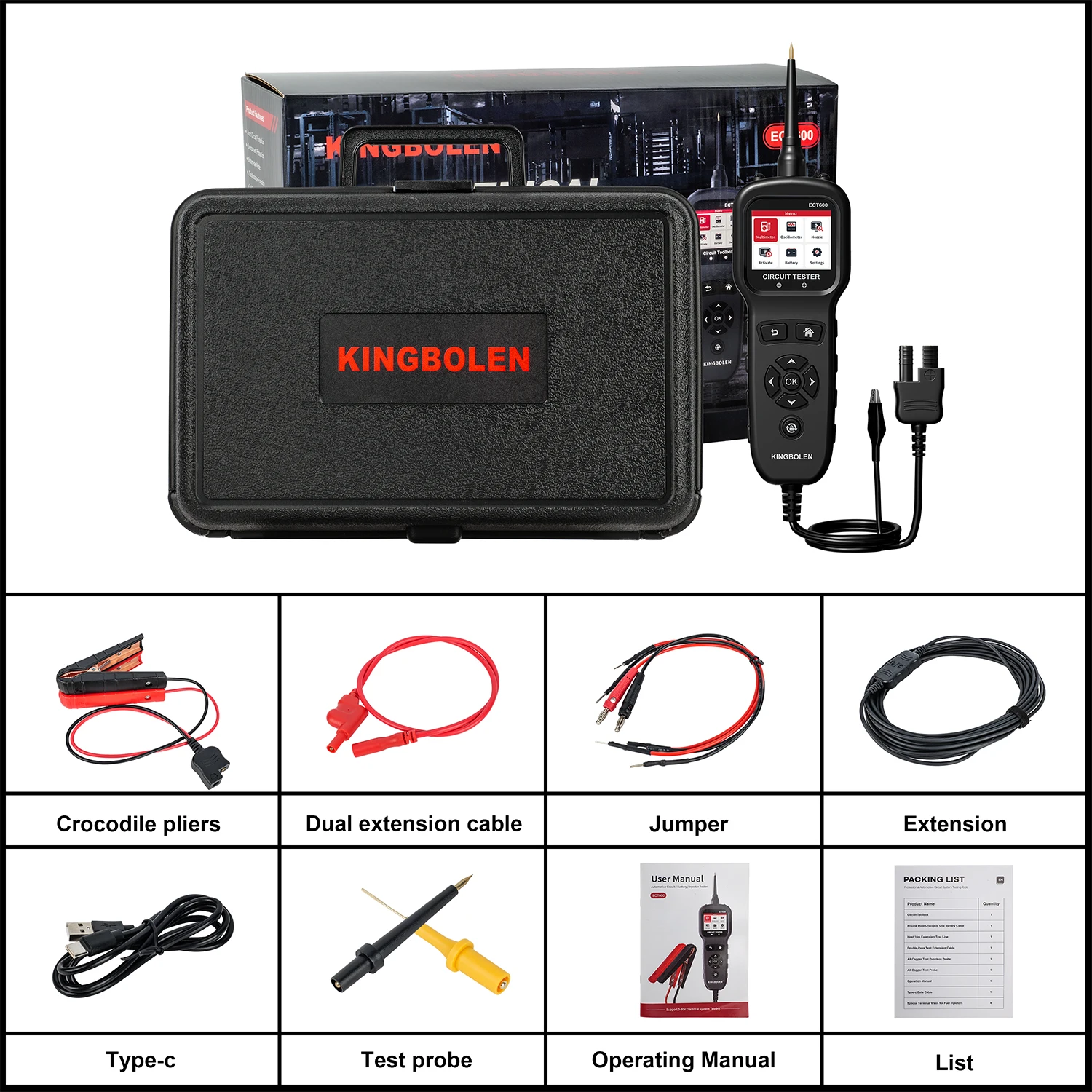
KINGBOKEN ECT600 Packing list :