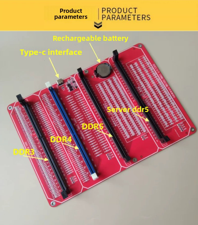
Desktop DDR3/4/5 Server Memory Module Tester—Computer Diagnostic Tool for Fault Detection (USB-Powered)
Memory Tester Product Overview:
This memory repair tester easily resolves various hardware issues with memory modules. The tester uses 136 indicator lights to measure each data line of the memory module, allowing you to easily locate the fault based on the LED brightness indicators.
Instructions for Use:
1. Insert the included battery (CR2032, 3.6V) into the battery compartment on the test card. Insert the memory module requiring repair into the slot on the memory tester. Press the test switch. If all indicator lights illuminate with consistent brightness, the memory module’s hardware is functioning properly. If any LEDs are flickering, it indicates poor contact at the gold fingers. If any LEDs are off, it indicates an open-circuit fault. Check whether the gold fingers are dirty, the resistors are damaged, or there is an open circuit. Use a multimeter to locate the fault based on the pin numbers corresponding to the LEDs. If one or more LEDs are unusually bright, it indicates a short circuit.
2. Once the memory module has passed the hardware test, consider a memory chip failure. Use the method of replacing chips one by one or test with appropriate software to identify the faulty memory chip.
Six Common Memory Repair Issues:
1: Wear caused by frequent insertion and removal of the gold fingers; oxidation caused by humid air; and poor contact caused by dust or grease on the gold fingers.
2: Damage to the resistor array. The resistor array on the memory module is easily damaged by impact during insertion and removal, or its resistance may increase due to performance degradation.
3: PCB trace breaks. When users insert or remove the memory module, if the gold fingers are not properly aligned with the motherboard slot or excessive force is applied, it can cause the PCB to bend. Since PCB traces are only 0.1 millimeters wide, improper use of the memory module can easily lead to trace breaks.
4: PCB bending, or thermal expansion and contraction of memory chips due to long-term use, can result in cold solder joints on the chip pins.
5: When replacing memory chips, uneven pressure during soldering can cause solder balls to form, leading to short circuits or cold solder joints.
6: A short circuit caused by leakage in the power supply’s filter capacitors. Damaged or malfunctioning memory chips.