Fast shipping to US!
This item will be shipped from US local warehouse by UPS. US Customers (except for Alaska, Hawaii & Puerto Rico) will receive this item fastly.
The more importance is that US customers dont need to pay Import Custom duty & fees. (Becuase it is domestic shipping)
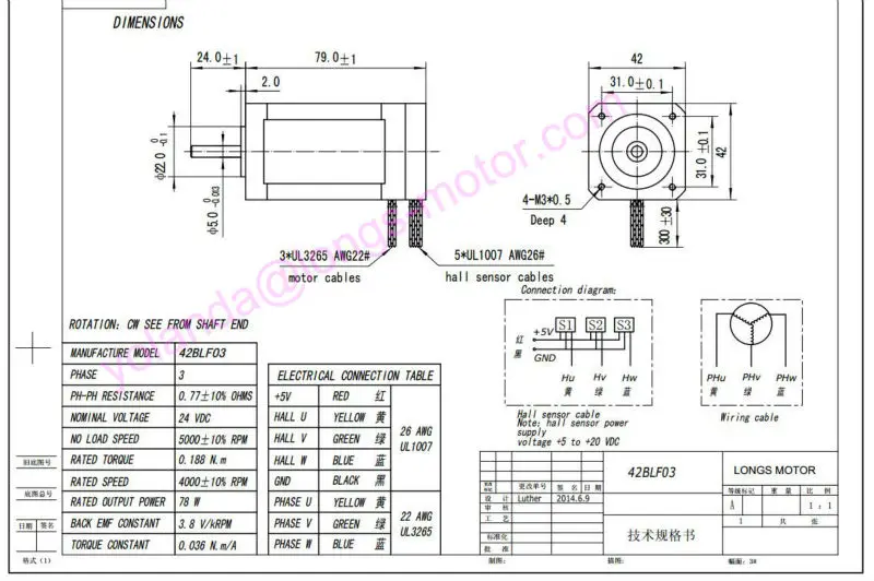 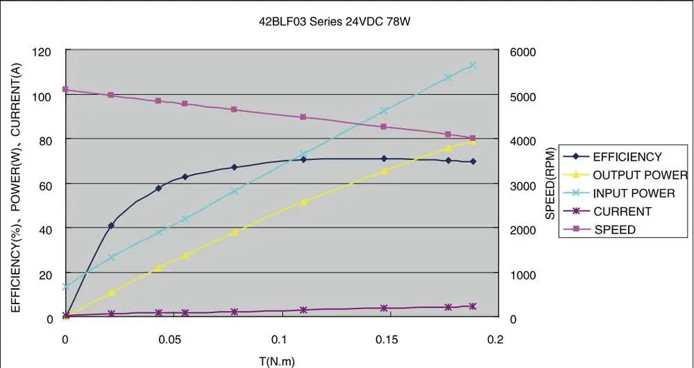 | |||||||||||||||||||||||||||
● SPWM,Speed/Current alike close loop technology, smooth rotation
l Smooth torque output within speed range (8000 rpm Max.)
l 1:75 Max. speed regulation ratio
l 60°/300°/120°/240°Electrical angle adjustable
l Speed regulation: potentiometer adjust / Analog input
l Run/Step、Quick Brake、CW/CCW rotation shift
l Speed output、Alarm output(O.C.)
l Over current、over voltage、stall、missing speed Alarm
Parameters
Electrical Parameters(Tj=25ºC)
Power | 24~50VDC, Capacity:up to motors |
Current output | Rated 15A,Peak 45A(≤3s) |
Driving mode | SPWM |
Insulation Res. | >500MΩ |
Dielectric Strength | 500V/Minute |
Weight | About 300g |
Ambient requirement
Cooling | Self cool |
Environment | Keep away from oil, dust, and acid gas |
Temperature | 0ºC~+50ºC |
Humidity | <80%RH |
Vibration | 5.7m/s2。Max. |
Storage temp. | -20ºC~+125ºC |
Function description
Power Supply: DC+ ; DC-
Voltage: 24~50DC,normally Linear Power Supply applied(appendix),ripple voltage higher than 50V may damage driver. The output current of LPS shall be 60%more than that of driver. In case of switching power supply(strongly recommended)applied, please pay attention to the current shall meet motor’s current.
Attention: incorrect connection may cause driver damaged.
Speed regulation choice(RV ; AVI)
1. Setup speed by potentiometer (RV).The dipswitch SW2 must be ON status to enable this function. CW rotate the potentiometer will increase speed. CCW- speed down.
2. Setup speed by analog input (AVI). The dipswitch SW2 must be OFF status to enable this function.。AVI terminal accept 0~5V voltage or PWM signal from controller。AVI terminal with input resistance of 100K,current consumption≤5mA。
Reference table
SW2 | Command to | Speed adjust | Comman | Current |
ON | RV | CW—speed up,CCW—speed down | - | - |
OFF | AVI | 0~5V analog input | 0~5V volage | ≤5mA |
OFF | AVI | PWM | 1KHz duty cycle | - |
Only one of above two modes can be used to adjust speed (another mode shall be enabled). Once AVI terminal applied, (RV) potentiometer shall be CCW turned to Min. position。PWM signal are 5V TTL level.
Run/Stop(ENBL)
ENBL terminal is applied to control motor Run/Stop,Common positive terminal is +5V.
Optical coupler short circuit make motor run, it open circuit make motor stop.
See below circuit
CW/CCW Rotation(F/R)
F/R terminal is applied to shift motor rotate direction, common positive terminal is+5V.
Motor run in CCW when optical coupler is short circuit, motor run in CW when optical coupler is open circuit.
Attention:don’t change the connection sequence of phase wires of motor to shift rotate direction.
Motor Brake Command(BRK)
BRK terminal applied to stop rotation quickly. Motor will stop normally within 50ms. But inertia of load can’t exceed 2 times of motor inertia, otherwise brake will cause driver alarm.
Time of acceleration and deceleration must be put into controller in case of too big load inertia,
And please don’t use brake function in such condition.
The optical coupler short circuit will brake motor,optical coupler open circuit release motor to run.
Setup different electrical angle
Dipswitch SW1 can be setup to fit motors with different electrical angel
SW1 | |
ON | 120°or 240°hall signal,they are in opposite rotation direction |
OFF | 60°or 300°hall signal, they are in opposite rotation direction |
Motor rotation speed output(SPEED)
Pulse generated by driver are proportioned with motor speed,(isolated O.C. output) it can be increased to be a random level. 6 multiple frequency processed output.
Motor speed=60×SPEED(pulse freq.)/pulses per rev. of motor;p.p.r=motor pole pairs×6
Alarm output(ALM)
Driver will enter protection mode and stop motor running in case of OVER CURRENT, OVER VOLTAGE, SHORT CIUCUIT, MOTOR STALL arise,LED on driver will be light, and ALM signal will be available. Please cut off
driver’s power supply,check wiring and voltage. High voltage is not permitted for big inertia motor, as it may cause run/stop frequently and over voltage alarm. Circuit of this function refer to pic. 2.
Terminals description
Terminal mark | Description |
DC+;DC- | Voltage supply to driver |
U;V;W | To motor leads. Make sure correct connection to motor leads. |
REF+;REF-;HU;HV;HW | Hall sensor connection,REF+;REF- are for hall power supply. Make sure correct connection to halls. |
AVI;ENBL;F/R;BRK;Vcc | Controls input,see below picture |
SPEED;ALM | Signal output,(O.C.) |
Appendix:linear power supply circuit
TX: Isolating transformers
VDC+≈1.414×Vout, Vout suggested to be AC21~28V for this driver
Capacity of transformer shall be decided by motor’s current
C1=100V/2200uF;C2=400V/0.22 uF;

Whats more, our products are mainly used in CNC machine, Carver machine, Automazation, Printer, Stage lighting and so on. If you have any questions about our products, please dont hesitate to contact me. And I will try my best to support you.After you payment,I will delivery to you right away.I will send manual to your e-mail,you need tell me your e-mail. Wish you have a good shopping. |