External Brake Resistor - AX2090-BW5x-xxxx
Appropriate use
The brake resistors from the AX2090-BW5x-xxxx series are exclusively designed for direct application with an AX5000 series servo drive or the AX5021 brake module. They are designed for installation as components in electrical installations and machines together with the servo drive or the brake module, and this is their only purpose.
Scope of supply
The scope of supply includes the following components:
- Brake resistor from the required performance class
- Technical documentation
- Packaging
If one of the components is damaged please notify the logistics company and Beckhoff Automation GmbH immediately.
Safety rules
The responsible staff must ensure that the application or use of the products described satisfy all the requirements for safety, including all the relevant laws, regulations and guidelines.
 DANGER | Serious risk of injury through electric shock! |
Caution - Risk of injury through hot surfaces! Even when the AX5000 is disconnected from the mains voltage, dangerous voltage continues to be present at the "X02" terminals of the DC link for 5 minutes. Wait until the DC link capacitors are discharged before touching live terminals. The voltage measured between the DC+ and DC- terminals (X02) must have fallen below 50 V. |
 WARNING |
| The temperature of the brake resistor housing surface may reach over 200 °C. Please ensure that the housing has cooled down below 40 °C before touching it. |
 |
| It is essential to observe chapter "Product overview-->Guidelines and Standards-->UL-Listing" if you wish to operate an AX5000 in an economic area that requires a UL-Listing. |
Product description
 Attention |
| The brake resistor may only be connected to individual AX5000 devices or AX5021 brake modules. It must never be used in a drive system without the AX5021 brake module, since this may lead to its destruction through overload. |
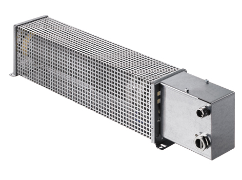
The external brake resistors of the AX2090-BW5x-xxxx series are able to convert the dynamic energy generated during braking of a servomotor into heat. The series covers a wide continuous power and peak power range. The built-in temperature switch enables the system to respond immediately to any overload of the brake resistor through analysis in the AX5000 or the PLC. All brake resistors of the AX2090-BW5x-xxxx series are UL and CSA approved.
Attention |
| The built-in temperature switch must be monitored, so that the machine can be stopped in a controlled manner and switched off in the event of an overloading of the brake resistor. |
Type key

Mechanical installation
Dimensions and technical data
| Type | Nominal capacity [W] * at 40 °C | Resistance [W] | O [mm] | R [mm] | H [mm] | M [mm] | U [mm] | Weight [kg] | AX5000 |
|---|---|---|---|---|---|---|---|---|---|
| AX2090-BW50-0300 | 300 | 47 | 349 | 92 | 120 | 230 | 64 | 2 | AX5x01 - AX5112 |
| AX2090-BW50-0600 | 600 | 47 | 549 | 92 | 120 | 430 | 64 | 3 | AX5x01 - AX5112 |
| AX2090-BW50-1600 | 1600 | 47 | 649 | 185 | 120 | 530 | 150 | 5,8 | AX5x01 - AX5112 |
| AX2090-BW51-1000 | 1000 | 23 | 749 | 92 | 120 | 630 | 64 | 4 | AX5118 - AX5193 |
| AX2090-BW51-3000 | 3000 | 23,4 | 490 | 355 | 255 | 380 | 270 | 8 | AX5118 - AX5193 |
| AX2090-BW51-6000 | 6000 | 23,2 | 490 | 455 | 255 | 380 | 370 | 12 | AX5118 - AX5193 |
*) 4% output reduction per 10 K temperature difference
Mounting positions and distances
(A) = vertical installation is only permitted according to the diagram (terminal box facing downwards).
(B) = horizontal installation
For all mounting positions the following minimum distances must be adhered to:
200 mm to adjacent components, walls etc. and 300 mm to components, ceilings etc. above. If the device is installed vertically (A), the minimum distance to components, floors etc. below is 200 mm in order to allow unobstructed flow of air to the brake resistor.
Electrical installation
DANGER |
| Disconnect the AX5000 from the mains before installing the brake resistor! Even when the AX5000 is disconnected from the mains voltage, dangerous voltage continues to be present at the "X02" terminals of the DC link for 5 minutes. Wait until the DC link capacitors are discharged before touching live terminals. The voltage measured between the DC+ and DC- terminals (X02) must have fallen below 50 V. |
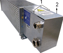
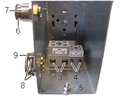
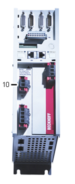
Remove the two screws (1) and remove the cover (2) in direction of the arrow. Connect an adequately dimensioned cable (see section Cables) to the terminals (3) of the resistor and the earthing stud (5) and take it out of the terminal box through the strain-relief assembly (9). Ensure adequate strain relief with the two screws (8). Connect the other side of the cable to the DC link contact connector X2 (10) of the AX5000. The connector is supplied with the AX5000. Connect the earthing cable to the earthing conductor of the control cabinet.
Connect an adequately dimensioned cable to the potential-free N/C contact (4) of the temperature switch and take it out of the terminal box through the strain-relief assembly (7) (see section Temperature switch). Ensure adequate strain relief with the nut (6).
Install the cover (2) in reverse order.
 |  |  |
Cables
We recommend Beckhoff motor cables for connecting the brake resistors.
WARNING |
| The brake resistors become very hot. Only use cables with adequate heat resistance. |
Attention |
| Use only shielded cables. |
Type | Brake resistor | Temperature switch | ||
|---|---|---|---|---|
| [mm2] | [AWG] | [mm2] | [AWG] | |
| AX2090-BW50-0300 | 1,5 | 16 | 0,75 | 18 |
| AX2090-BW50-0600 | 1,5 | 16 | 0,75 | 18 |
| AX2090-BW50-1600 | 1,5 | 16 | 0,75 | 18 |
| AX2090-BW51-1000 | 2,5 | 12 | 0,75 | 18 |
| AX2090-BW51-3000 | 2,5 | 12 | 0,75 | 18 |
| AX2090-BW51-6000 | 2,5 | 12 | 0,75 | 18 |
We recommend wire end sleeves.
Temperature switch
Attention |
| The temperature switch is only used for temperature monitoring. The brake resistor is not switched off. |
The temperature switch has a potential-free N/C contact, which enables immediate response to any overload of the brake resistor through analysis in the AX5000 or the PLC. Connect the cable directly to a free input of plug "X06". Then parameterise it such that the AX5000 stops the motor(s) with an emergency ramp or the PLC reads and processes this input.
Type | Switching temperature | Switching current 24 VDC er 230 VAC |
|---|---|---|
| [°C] | [A] | |
| AX2090-BW50-0300 | 180 | 2 |
| AX2090-BW50-0600 | 180 | 2 |
| AX2090-BW50-1600 | 180 | 2 |
| AX2090-BW51-1000 | 180 | 2 |
| AX2090-BW51-3000 | 85 | 2 |
| AX2090-BW51-6000 | 85 | 2 |
Short-term capacity
Brake resistors are usually not operated continuously, but only exposed to short-time duty. In the following section the permitted short-term capacity is calculated based on the continuous power, overload factor and duty cycle.
Duty cycle
The duty cycle is a relative value that depends on the switch-on time (ton)and the cycle time. Cycle times up to 120 sec. are used directly in the calculation. Should the cycle time exceed 120 sec., the maximum relevant cycle time of 120 sec. is used in the calculation.
 |  | Example 1 ton = 60 s Cycle time = 280 s Duty cycle = 50 % | Example 2 ton = 40 s Cycle time = 180 s Duty cycle = 40 % |
Overload factor
 |  |
Calculation formula:
Short-term capacity = continuous power x overload factor
Overtemperature and continuous power at 100% duty cycle
If your application requires a higher continuous power than the specified nominal capacity, you can accept this state if a higher brake resistor temperature is permitted. The following diagram shows the overtemperature v. the continuous power.
| Normal operating range, max. 130%: This operating range is recommended for maximum service life and error-free operation. Permitted operating range, max. 160%: Inadmissible operating range, more than 160%: |  |
Attention |
| Always ensure adequate ventilation of the brake resistor, since the temperatures of the housing surface may exceed 200 °C. |
Ship to a Confirmed physical address only,
NO P.O.Box
Shiping worldwide
We usually ship in 3 days
No return accepted