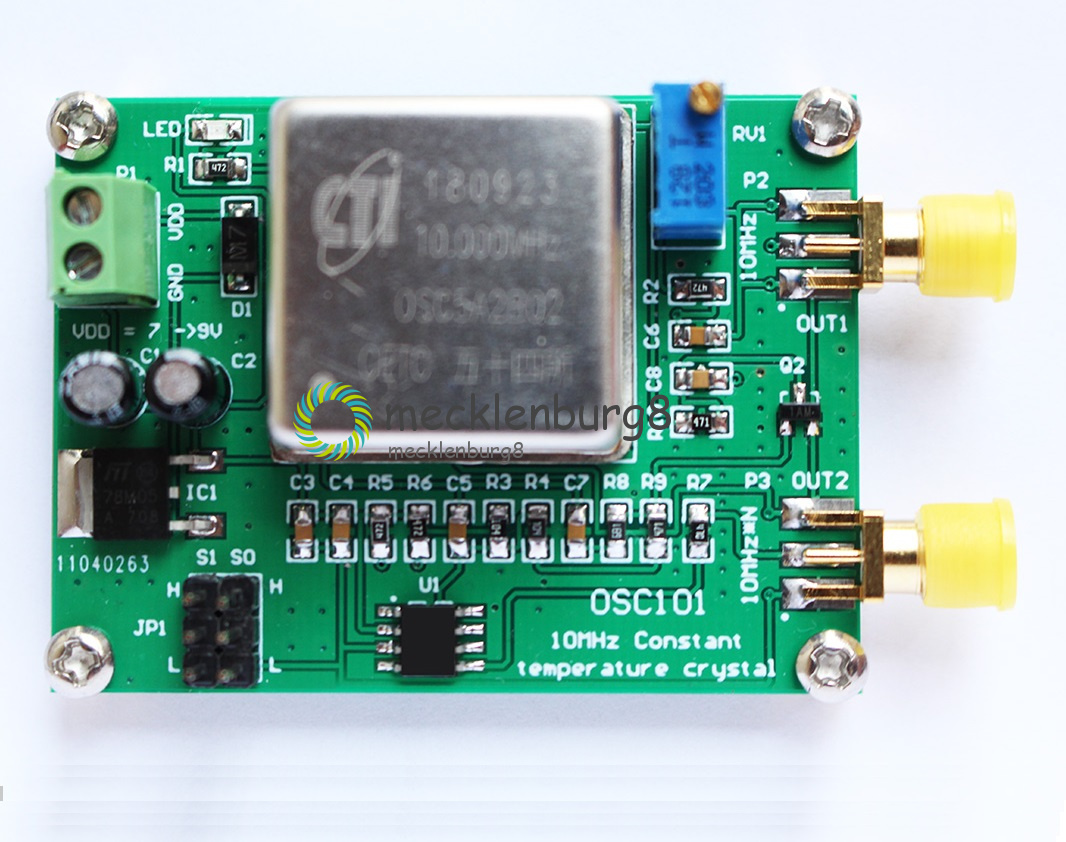
This module outputs the frequency accuracy of the 10MHz signal (+/-200ppb), has two signal outputs, and one is a standard 10MHz signal.
The other is a 10MHz multiplier signal. The multiplier signal has 9 selection frequencies, which are 2X, 3X, 3.125X, 4X, 5X, 5.3125X, 6X, 6.25X, 8X.
The different multipliers are selected by the JP1 jumper pin. Correct the deviation of the 10Mhz output frequency (+/-2.0ppm) with the RV1 potentiometer.
Wiring Terminals
1. P1: Power input interface; (7~9V).
2. P2: 10MHz signal output interface; (10Mhz amplitude: 3Vpp) SMA interface
3. P3: N frequency output interface of 10MHz signal; (N*10Mhz amplitude: 5Vpp) SMA interface
4. RV1: Correct the deviation of the 10Mhz output frequency (+/-2.0ppm)
Jumper Functions
5.JP1 jumper needle selection
S1=0,S0=0, OUT = 4X
S1=0,S0=M, OUT = 5.3125X
S1=0,S0=1, OUT = 5X
S1=M,S0=0, OUT = 6.25X
S1=M,S0=M, OUT = 2X
S1=M,S0=1, OUT = 3.125X
S1=1,S0=0, OUT = 6X
S1=1,S0=M, OUT = 3X
S1=1,S0=1, OUT = 8X
0 = connect directly to ground(L)
1 = connect directly to VDD(H)
M = leave unconnected(floating)
-
If you can't receive the product within 2 months (60 days), please contact with us,we promise to payback 100% of your money.
We ensure our products work normally before post.If the products is broken before arrival to you,all you should do is taking a photo to show us our broken product.We promise to payback 100% of your money. - If the item is defect when you receive it or you are not satisfied with it, please return it within 14 days for a replacement or money back. But the items must be back in factory condition. Please contact us and double check the return address before you return it.
- If is item is defective in 12 months, you can return it to us. We will send you a new replacement after receiving the defective item.
- 1. We only ship to the confirmed address provided by eBay. please make sure your ebay address is 100% matches the address you would like us to ship to. If not, please let us know before we sent you the package, or we will not be responsible for any loss. hope you could understand.
2. Orders will be processed instantly and dispatched within 1-3 business days except hoilday, so we do NOT accept any email/message note after you place orders.
- EBAY Managed Payment. But we only Accept your Ebay Address, please Make sure it's 100% right.
Payment must be received in 5 business days of auction closing.
Please leave note for your special request (e.g. Colors or Size) in PayPal when you pay the order.
Any special request cannot be accepted after 24 hours of payment, because most of orders will be processed instantly and same day dispatched.
* When you satisfied with our product and services please leave us positive feedback.
* If you have got the package, please confirm "Delivery on time" For us.
* If a problem occurs, contact us immediately with any email request.
* Just contact us using the " Ask the seller a question" link on eBay.
Am 08.11.21 hat der Verkäufer die folgenden Angaben hinzugefügt: