Human Presence Detection Radar Module 60GHz LD6003G for Smart Home / 60GHz Non-contact Breathing Heart Rate Detection Sensor LD6003
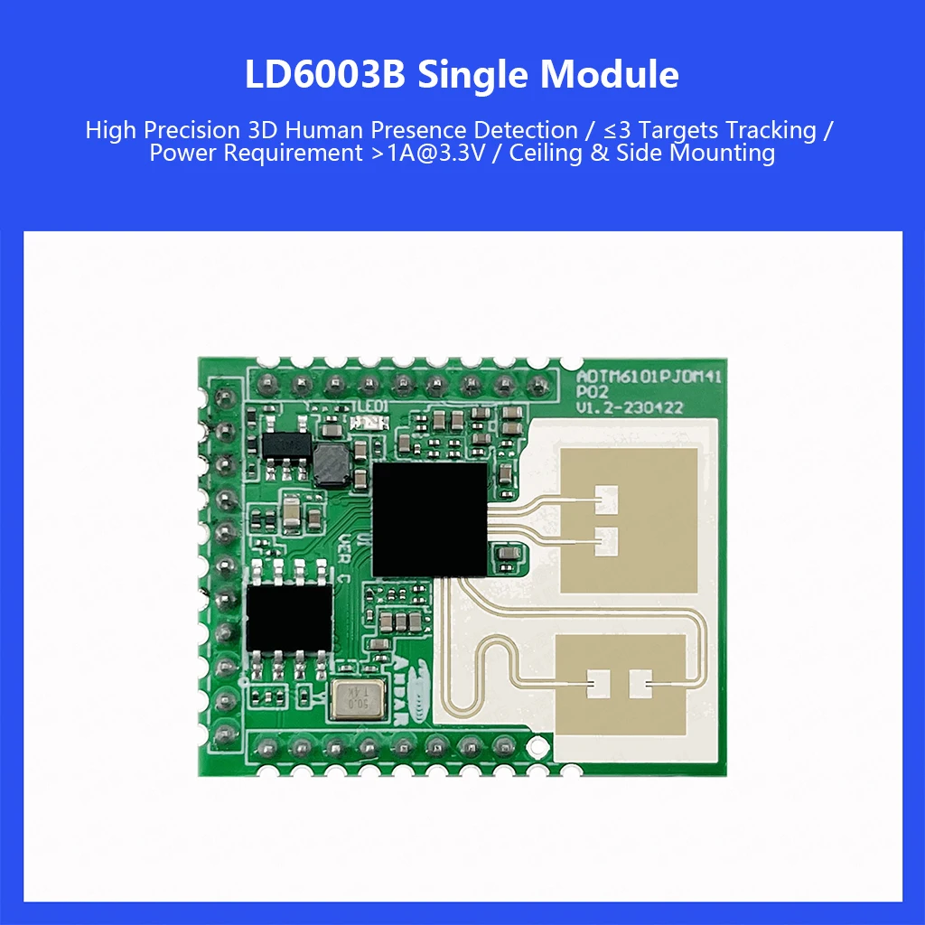
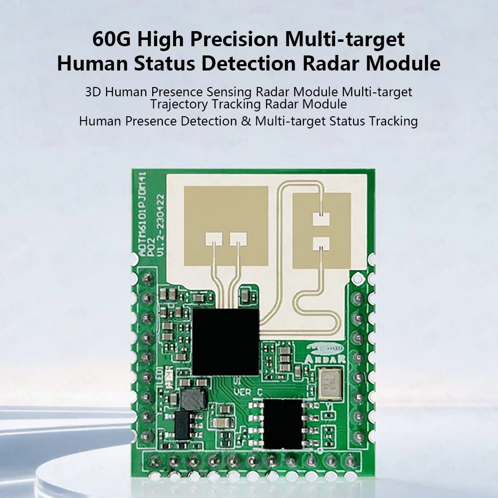
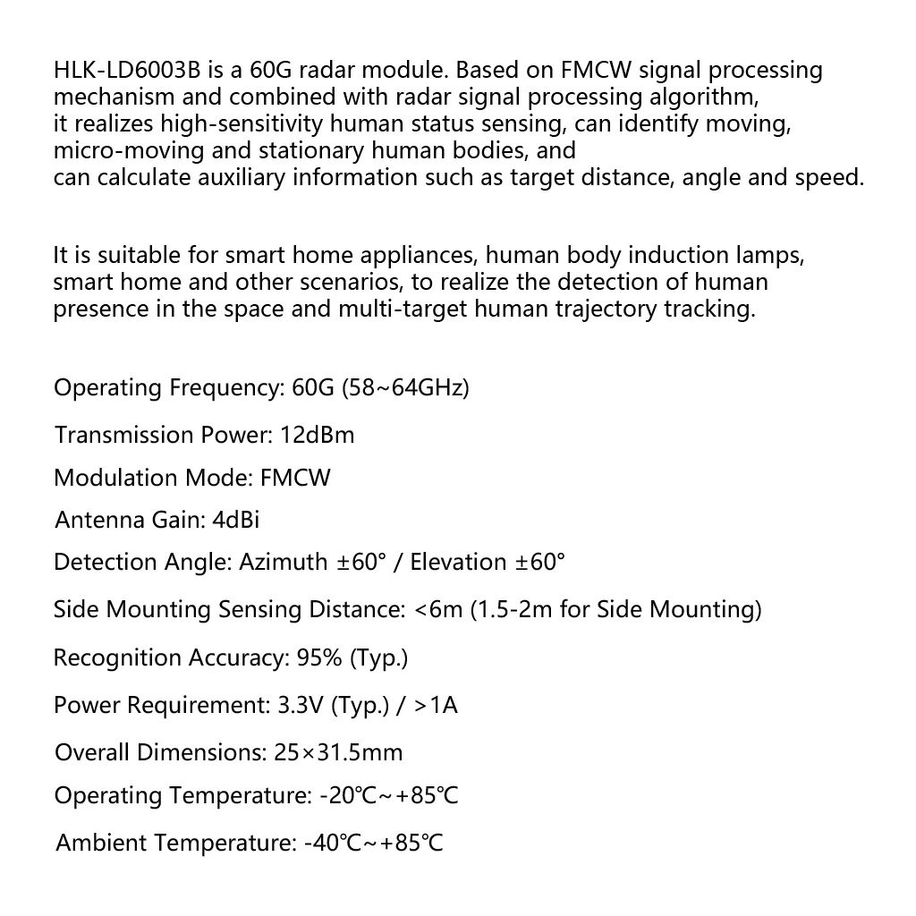
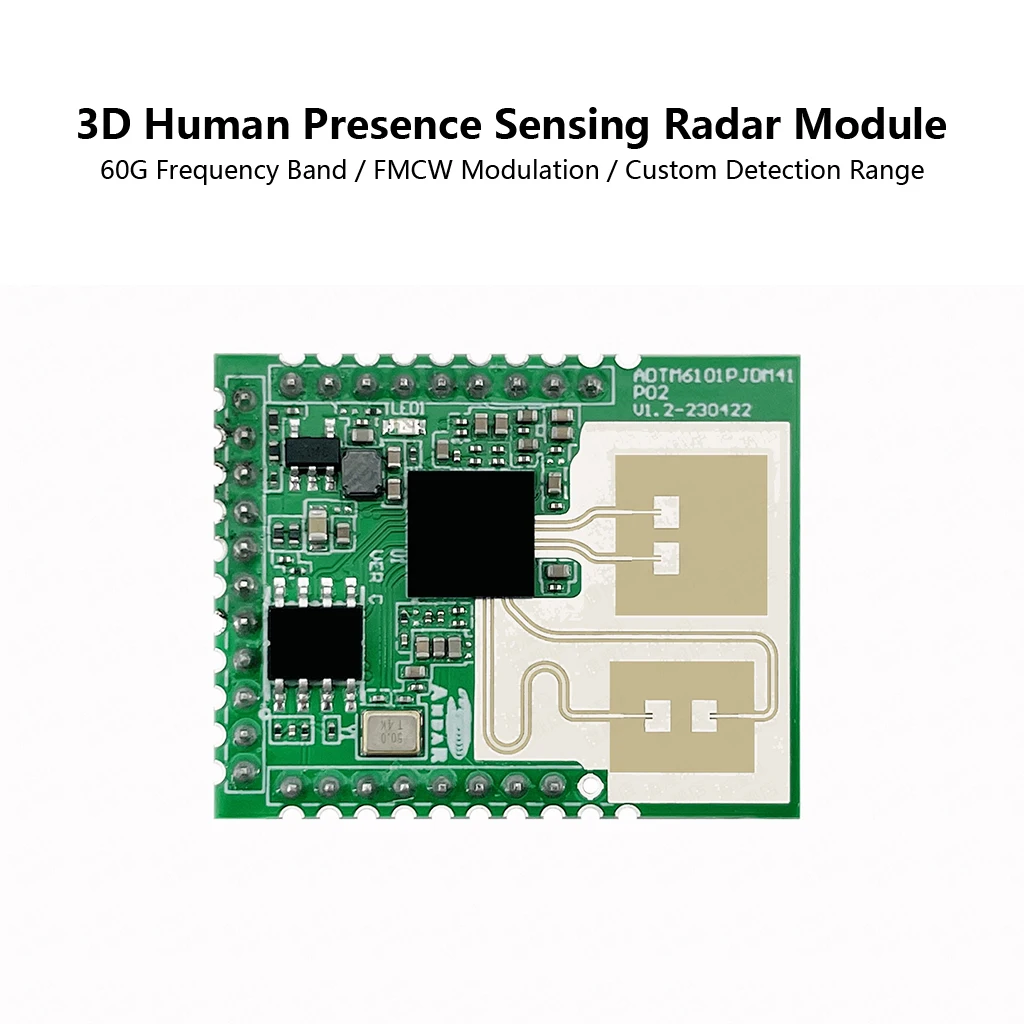
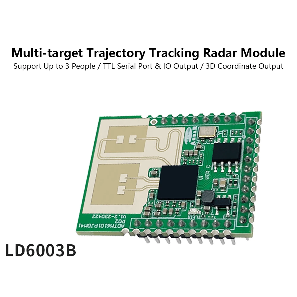
60G High-Precision Multi-Target Human State Detection Radar Module (HLK-LD6003B)
1. Product Overview
• Model: HLK-LD6003B
• Technology: FMCW (Frequency Modulated Continuous Wave) radar.
• Core Functions:
◦ Human presence detection and multi-target tracking (up to 3 targets).
◦ Recognizes moving, micro-moving, and stationary humans.
◦ Calculates target distance, angle, speed, and outputs 3D coordinates.
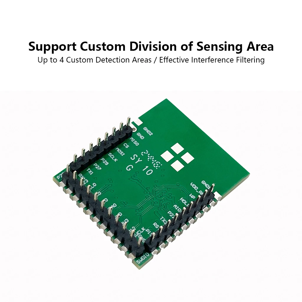
◦ Supports customizable detection zones (up to 4 areas).
2. Key Specifications
Parameter Specification
Frequency 60 GHz (58 ~ 64 GHz)
Transmit Power 12 dBm
Modulation FMCW
Antenna Gain 4 dBi
Detection Angle Azimuth ±60° / Elevation ±60°
Detection Range < 6 m (Side Mount: 1.5–2 m height)
Accuracy 95% (Typical)
Supply Voltage 3.3V (Range: 3.1V ~ 3.5V)
Current Requirement > 1A
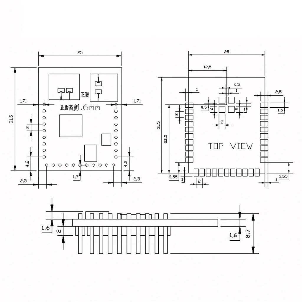
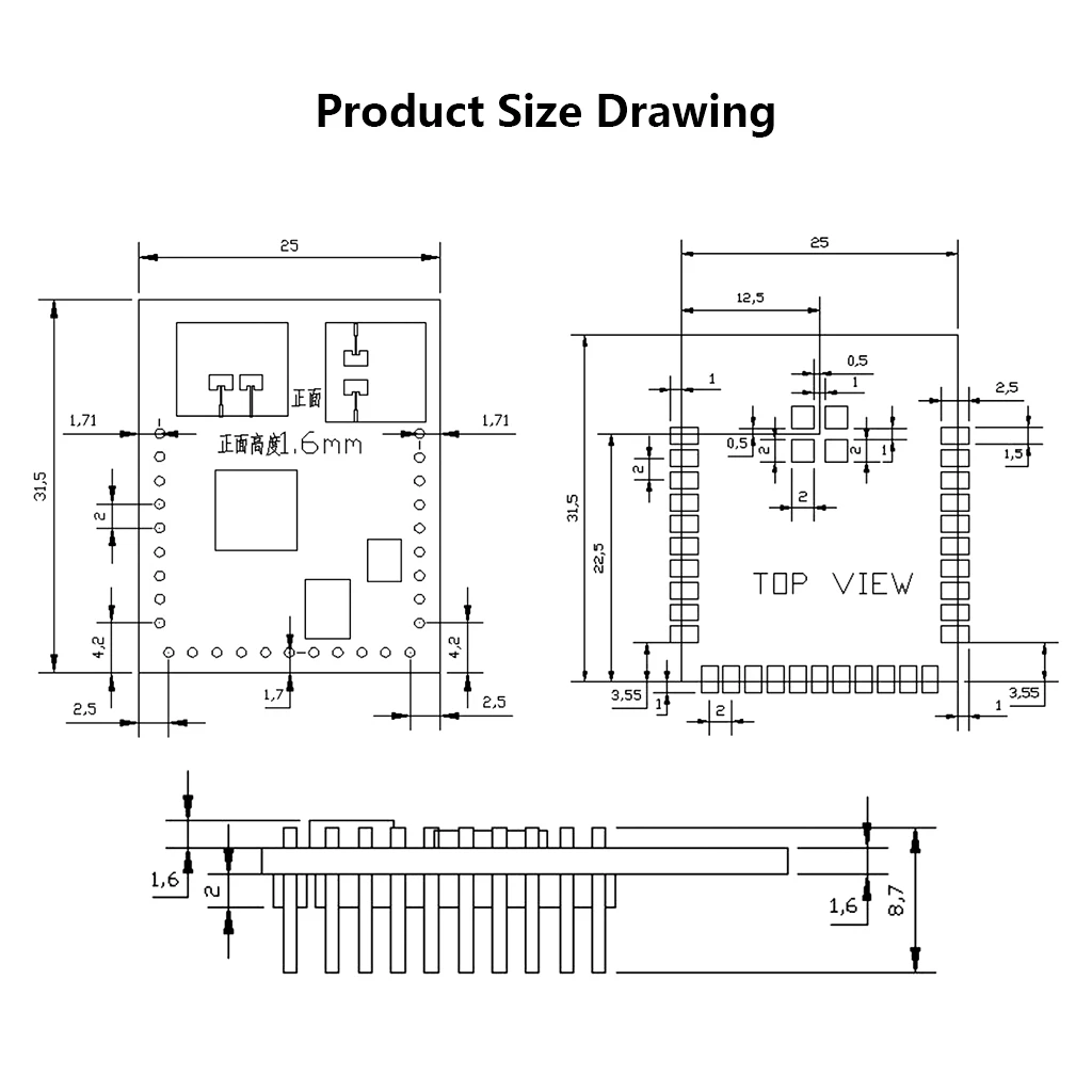
Dimensions 25 × 31.5 mm
Operating Temp. -20°C ~ +85°C
Storage Temp. -40°C ~ +85°C
3. Pin Definition (Key Pins)
Pin Name Description Notes
1 VDDRF External RF Power (1.35V) SMT only
2 WP Write Protect (Active Low) Flash function
3 HOLD Hold Signal Flash function
6 TX2 UART2_TX / GPIO Control output (e.g., relay)
7 RST Reset Input
8 P19 BOOT1 Boot config
10 SWDIO SWD Debug Data
11 SWCLK SWD Debug Clock
12 P12 BOOT0 Boot config
13 3.3V Power Supply Input
16 RX0 UART0_RX / GPIO
17 TX0 UART0_TX / GPIO Host communication
21 RX1 UART1_RX / GPIO
22 TX1 UART1_TX / GPIO
25 SCLK SPI0_SCLK / GPIO RF ADC output
26 MOSI SPI0_MOSI / GPIO RF ADC output
27 CS SPI0_CS / GPIO RF ADC output
28 MISO SPI0_MISO / GPIO
4. Boot Configuration
The module boots from internal Flash by default.
BOOT1 (Pin 8) BOOT0 (Pin 12) Mode
0 1 Internal Flash Boot
Note: Both BOOT pins have internal pull-ups. BOOT1 must be pulled LOW before startup.
5. Output & Interface
• UART Output: Default baud rate 115200, no parity. Outputs detection results via UART0 protocol.
• GPIO Output: Direct level output via TX2 pin (High: Human detected, Low: No one).
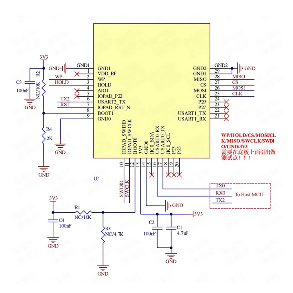
6. Reference Design & Peripherals
• Power Supply: Requires 3.3V with current capacity > 1A. If using DCDC, switching frequency must be ≥ 2 MHz with ripple ≤ 50 mV.
• Decoupling: Requires capacitors (e.g., 100nF, 4.7µF) near the power pins.
• Debugging: Use SWDIO (Pin 10) and SWCLK (Pin 11) for debugging.
7. Installation & Detection Range
• Ceiling Mount: Height 2.2 – 3 m.
• Side Wall Mount: Height 1.5 – 2 m, Max range < 6 m.
• Coverage: Conical detection area defined by ±60° azimuth and elevation.
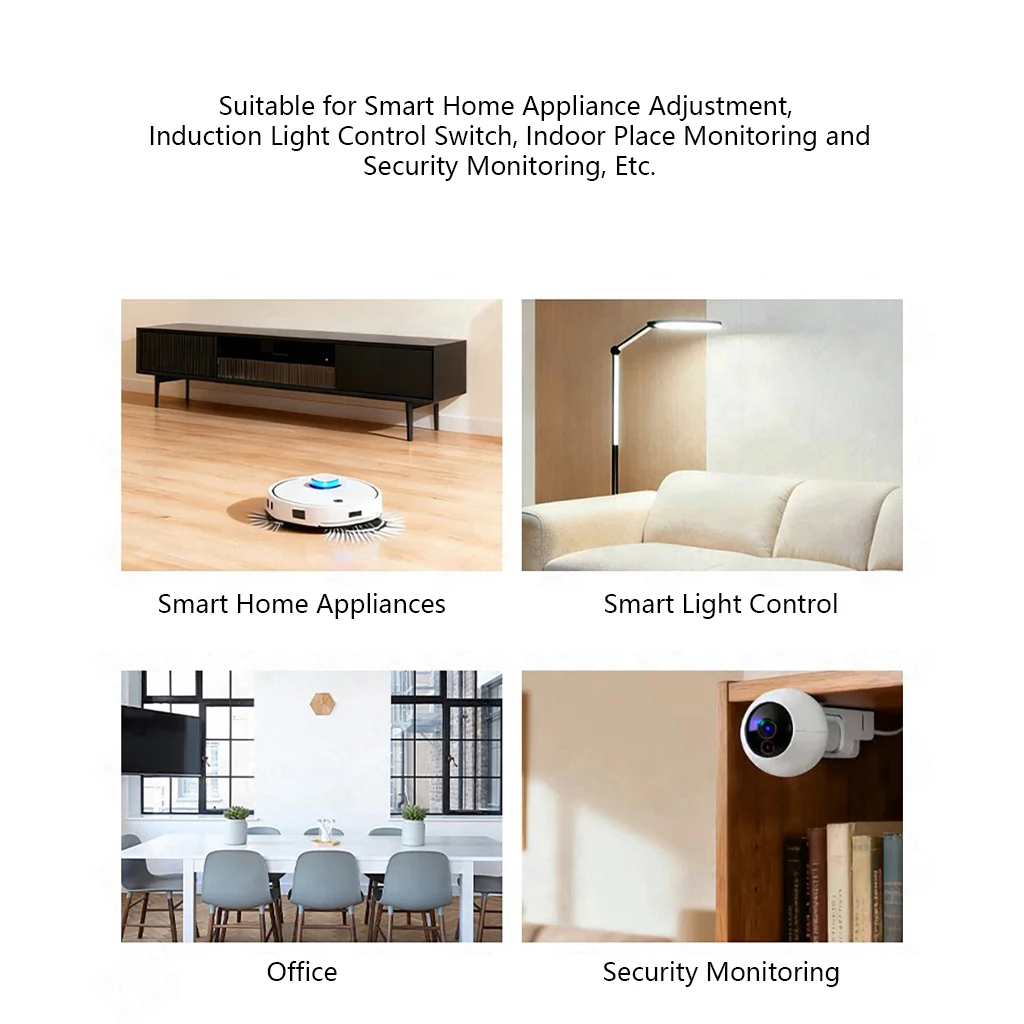
8. Application Scenarios
• Smart Home Appliances (presence sensing).
• Smart Lighting Control (auto on/off).
• Office Occupancy Monitoring.
• Security Surveillance Systems.
9. Additional Notes
• Detection distance varies with target RCS (Radar Cross Section) and environmental factors; fluctuations are normal.
• The module supports filtering interference through custom zone settings.
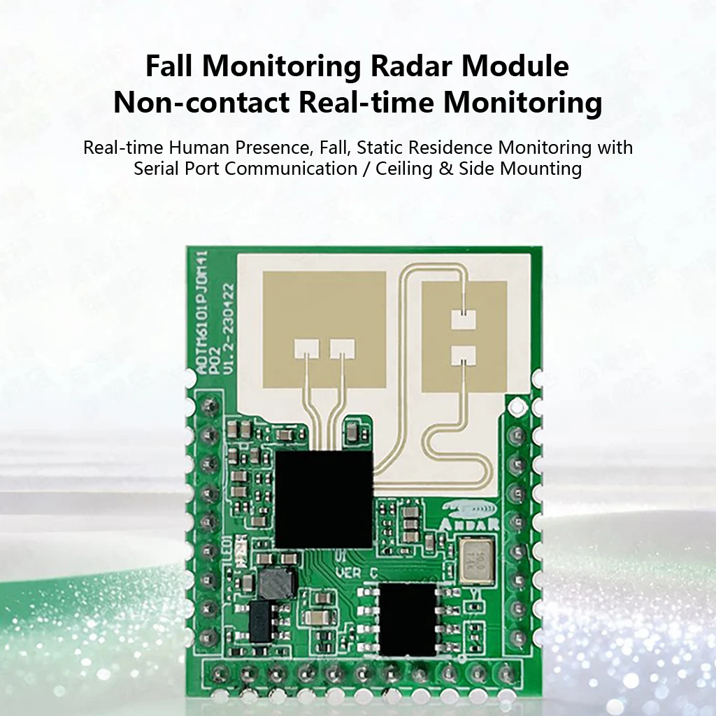
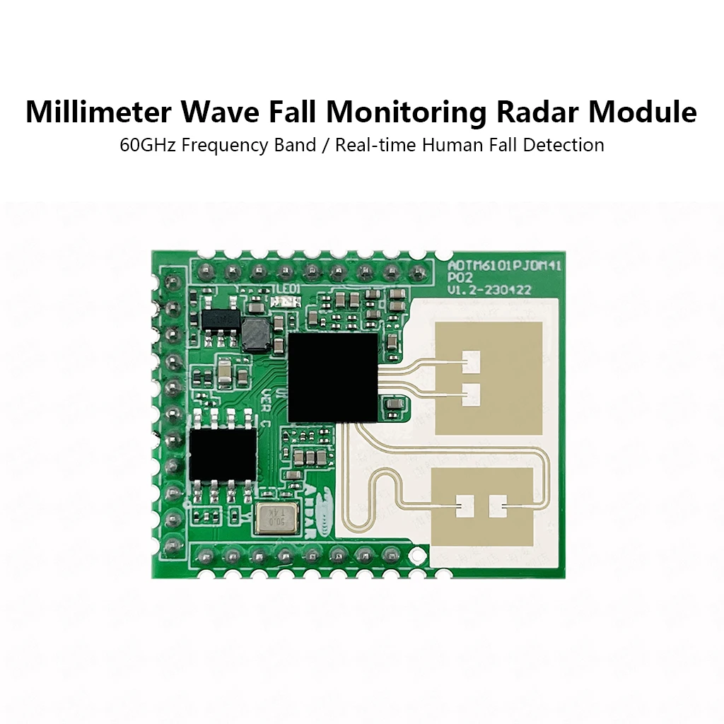
Fall Detection Radar Module (LD6003C)
1. Product Overview
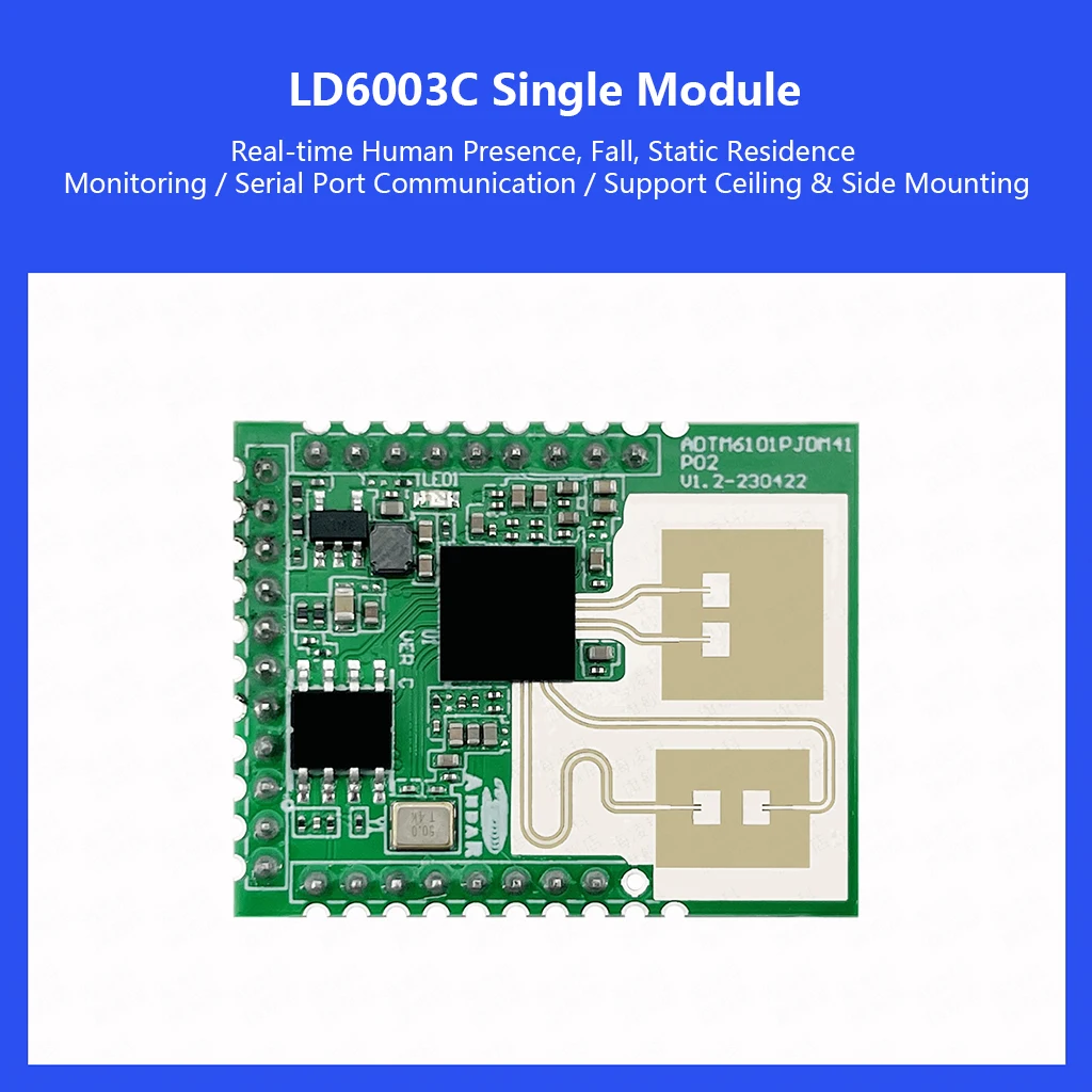
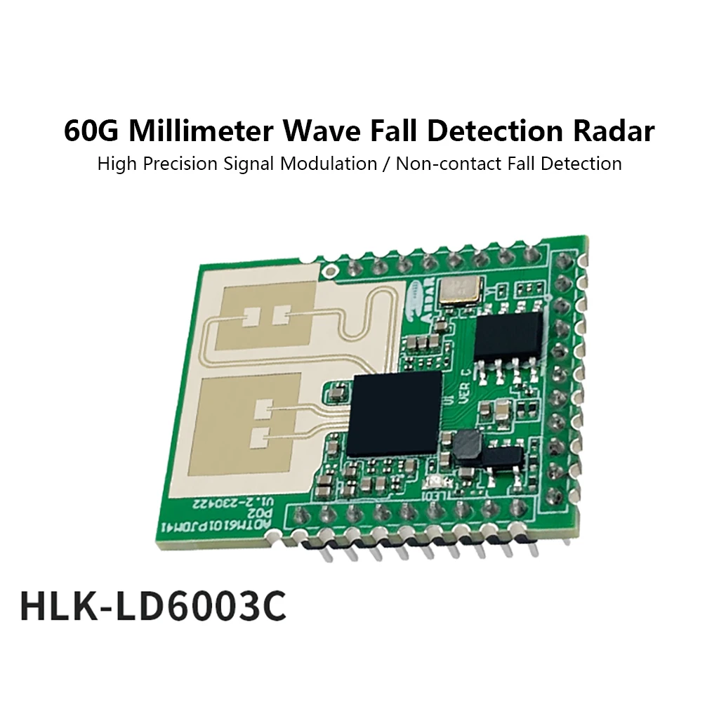
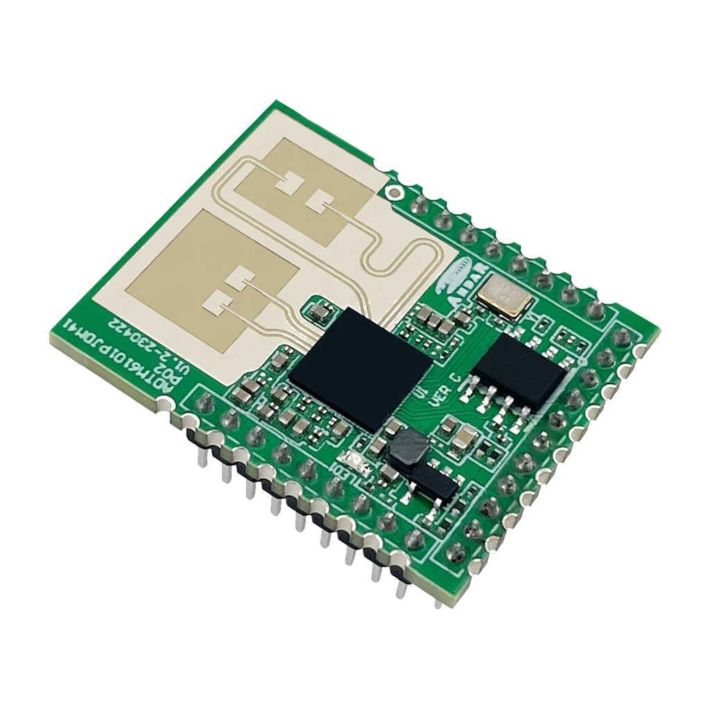
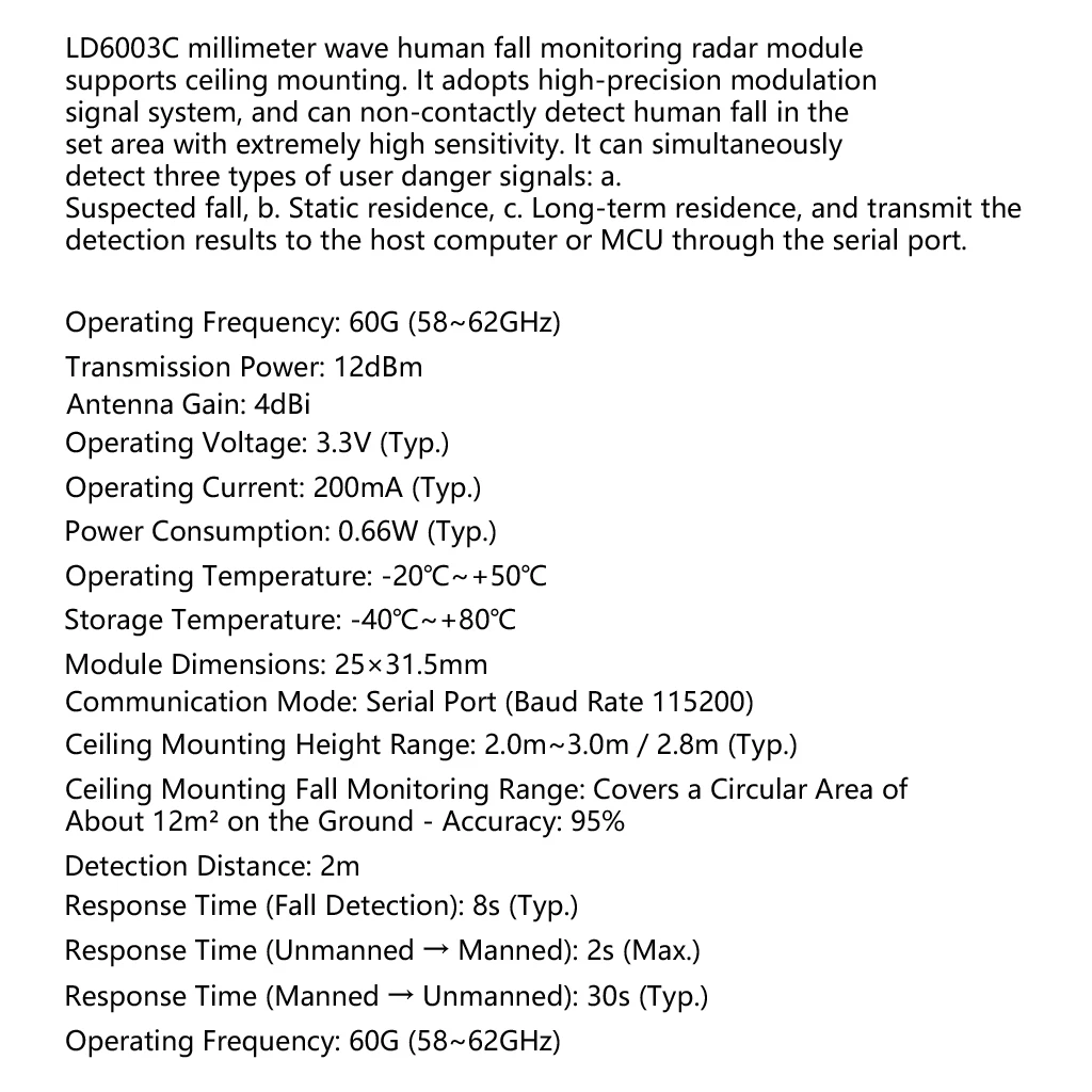
The LD6003C is a millimeter-wave human fall detection radar module. It supports ceiling mounting and uses a high-precision modulation signal system for non-contact real-time detection of dangerous signals such as human falls and stationary presence. Results are transmitted to a host computer or MCU via serial port.
2. Product Features
Parameter Value
Operating Frequency 60G (58~62GHz)
Transmit Power 12dBm
Antenna Gain 4dBi
Operating Voltage 3.3V (Typ.)
Operating Current 200mA (Typ.)
Power Consumption 0.66W (Typ.)
Operating Temp -20℃ ~ +50℃
Storage Temp -40℃ ~ +80℃
Module Size 25 × 31.5 mm
Communication Serial Port (Baud Rate 115200)
Ceiling Mount Height 2.0m ~ 3.0m / 2.8m (Typ.)
Monitoring Range Approx. 12m² circular area
Accuracy 95%
Detection Distance 2m
Fall Response Time 8s (Typ.)
No Person → Person 2s (Max.)
Person → No Person 30s (Typ.)
3. Mechanical Dimensions
• Top View: Approximately 25mm (Width) × 31.5mm (Height).
• Note: Pin spacing is 1.6mm (refer to the specific drawing for details).
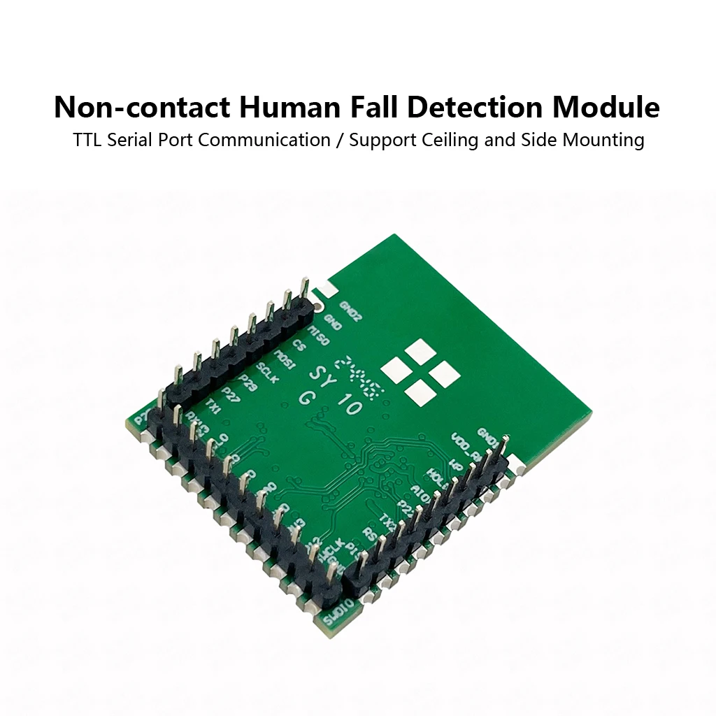
4. Pin Definition (Pin No. - Name - Description - Remarks)
Pin Name Description Remarks
1 VDDRF External RF Power / 1.35V -
2 WP Write protection active low Flash function pin
3 HOLD Hold device (without deselecting) Flash function pin
4 AIO1 Temperature index test interface Can be used as analog input
5 P22 interfaceGPIO_P22 / LDO_EXT_EN_H -
6 TX2 GPIO_P20 / uart2_txd Control output (e.g., relay)
7 RST Reset Signal Input -
8 P19 GPIO_P19 / boot1 Boot
9 GND0 GND Boot
10 SWDIO SWD Debug Signal -
11 SWCLK SWD Debug Clock -
12 P12 GPIO_P12 / boot0 Boot
13 3.3V POWER INPUT 3.3V -
14 GND GND -
15 SDA GPIO_P08 / IIC0_SDA -
16 RX0 GPIO_P01 / uart0_rxd -
17 TX0 GPIO_P00 / uart0_txd -
18 SCL GPIO_P07 / IIC0_SCL -
19 P23 IOPAD_P23 -
20 P25 IOPAD_P25 -
21 RX1 GPIO_P11 / uart1_rxd -
22 TX1 GPIO_P10 / uart1_txd -
23 P27 IOPAD_P27 -
24 P29 IOPAD_P29 -
25 SCLK IOPAD_P03 / SPI0_SCLK Can be used for RF ADC signal output
26 MOSI IOPAD_P06 / SPI0_MOSI Can be used for RF ADC signal output
27 CS IOPAD_P04 / SPI0_CS Can be used for RF ADC signal output
28 MISO IOPAD_P05 / SPI0_MISO -
29 GND1 GND Supports SMT package only
- GND2 GND Supports SMT package only
5. Reference Design (Peripherals)
• Power: 3.3V supply. Filter capacitors (e.g., 100nF) are recommended for VDDRF and 3.3V pins.
• Debugging: Connect SWDIO (Pin 10) and SWCLK (Pin 11) to the debugger. RST (Pin 7) can connect to an external reset circuit.
• Communication: Connect TX0/RX0 (Pin 16/17) to the host MCU UART. TX1/RX1 (Pin 21/22) are optional.
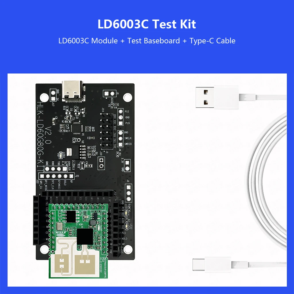
• Note: WP/HOLD/CS/MOSI/CLK/O/GND/3V3 must be soldered to the baseboard as test points.
6. Module Startup Configuration
BOOT1 BOOT0 Description
0 1 Internal Flash Boot
Pin 8 - BOOT1 must be pulled Low (Internally pulled up, force pull-down required)
Pin 12 - BOOT0 (Internally pulled up)
7. Function & Parameter Settings
• Interaction Types: ① Parameter Setting (Customizable/Default); ② Monitoring Data Reporting (Timed upload).
• Configurable Parameters:
Parameter Name Min Typ Max Unit Remarks
Installation Height 1.4 - 3.0 m Default 2.8m (Ceiling)
Installation Method - Ceiling - - -
Static Presence Duration - 5 - min Recommended to set longer
Long Stay Duration - 30 - min Server-side processing for continuous presence
8. Getting Started
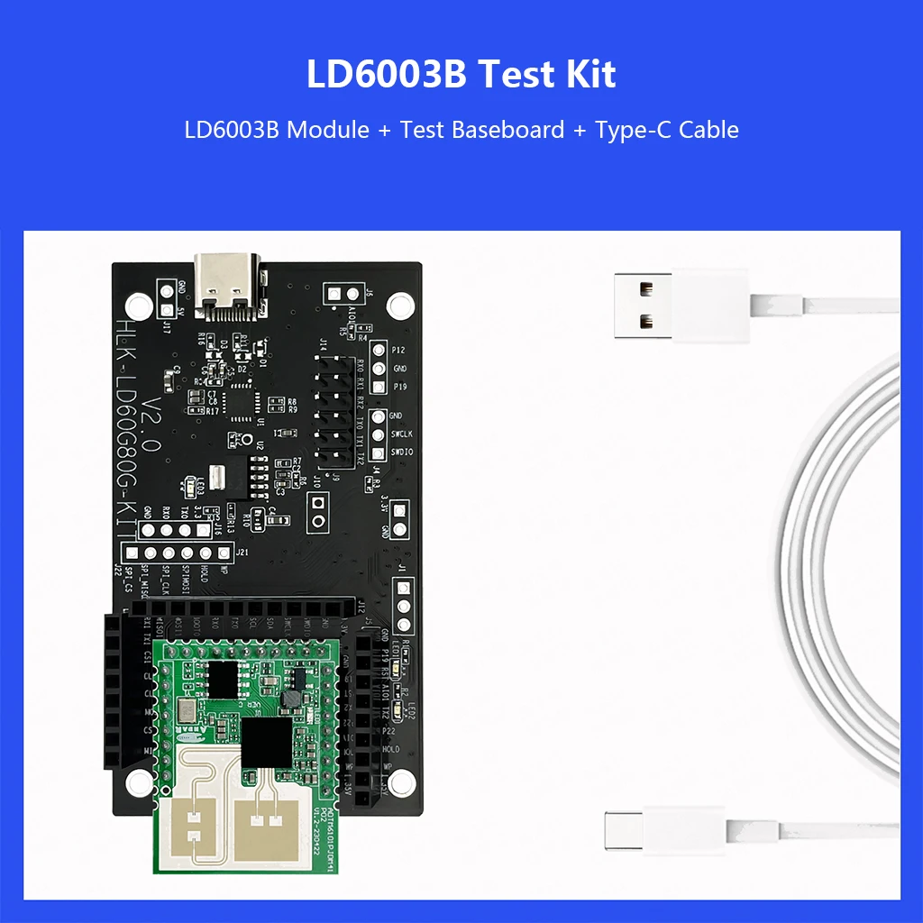
• It is recommended to use a test baseboard + evaluation software for development and testing. The software receives monitoring data, stores/displays graphics, and configures parameters.
• Evaluation Software UI: Allows device selection, serial port settings (Baud Rate 115200), viewing monitoring data/waveforms/logs, etc.