Garage Door Opener Wall Mounted Button 41A5273 Multi-Function Control Panel 78LM
WIRED CONTROL PANEL INSTALLATION INSTRUCTIONS
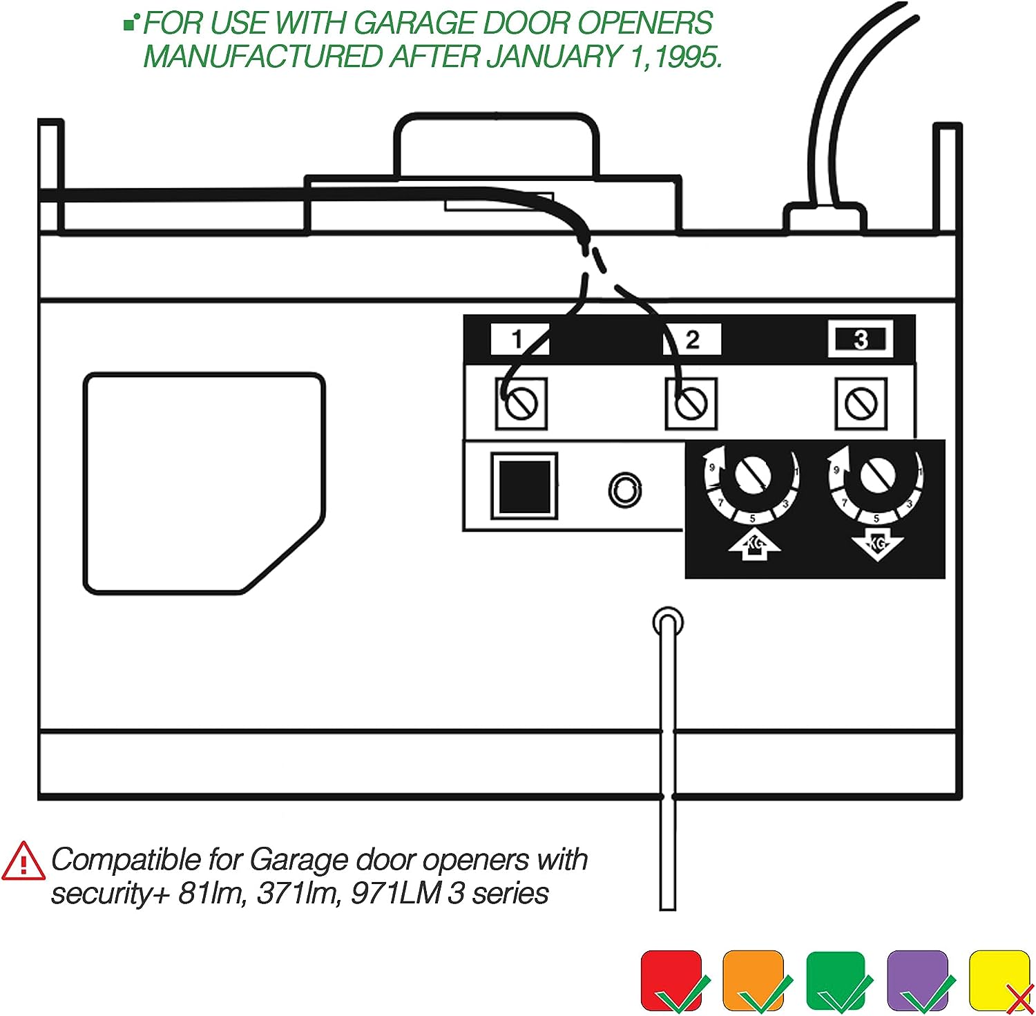
FOR USE WITH GARAGE DOOR OPENERS MANUFACTURED AFTER JANUARY 1,1995. To ensure proper function of your opener,remove all old or previous push buttons/wall control panels. Use only the enclosed door control for proper operation.To activate:Press and hold the Lock button for 2 seconds.The push button indicator light will flash as long as the lock is on.
To turn off:Press and hold the Lock button again for 2 seconds.The indicator light will stop flashing.Normal operation will resume.
The Lock feature will also turn off whenever the Learn button on the opener end panel is activated.

Specification:
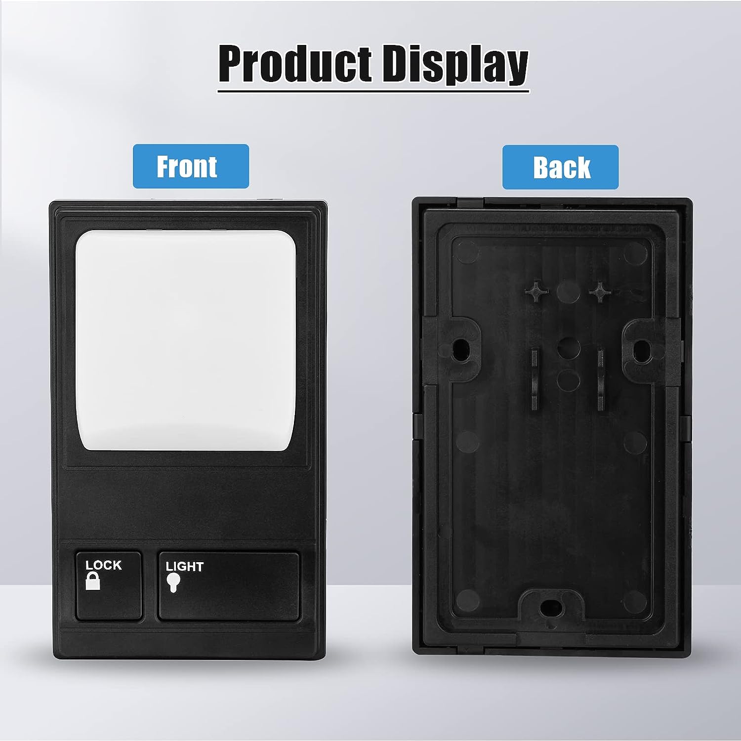
item color: Black
type: Wall Button
material: Plastic/ABS
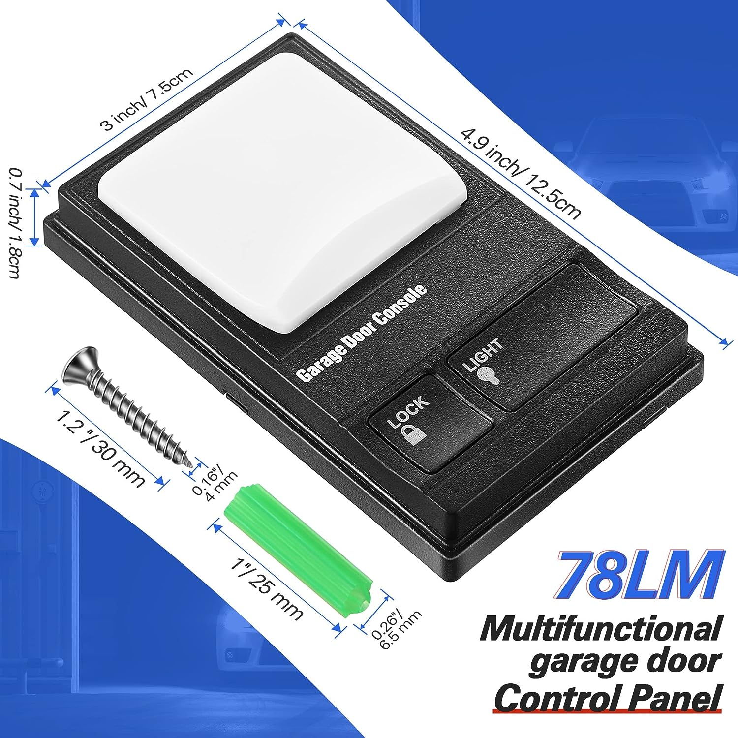
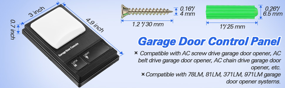
size: 4.9*3*0.7in
Fit Learn Button: Purple, Orange, Red, Green.
Fit For: Chamberlain, Sears, Master Mechanic, Garage Master, Wayne-Dalton and Raynor.
For 78LM 79LM 81LM 371LM 971LM
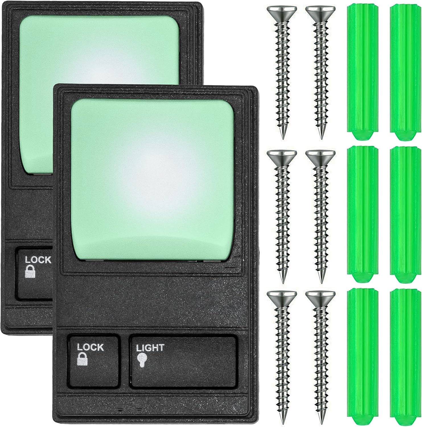
Package Included: 1 x Multi-Function Wall Console (Battery is not included)
Features:
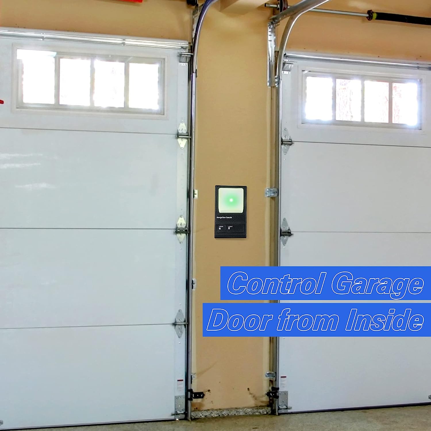
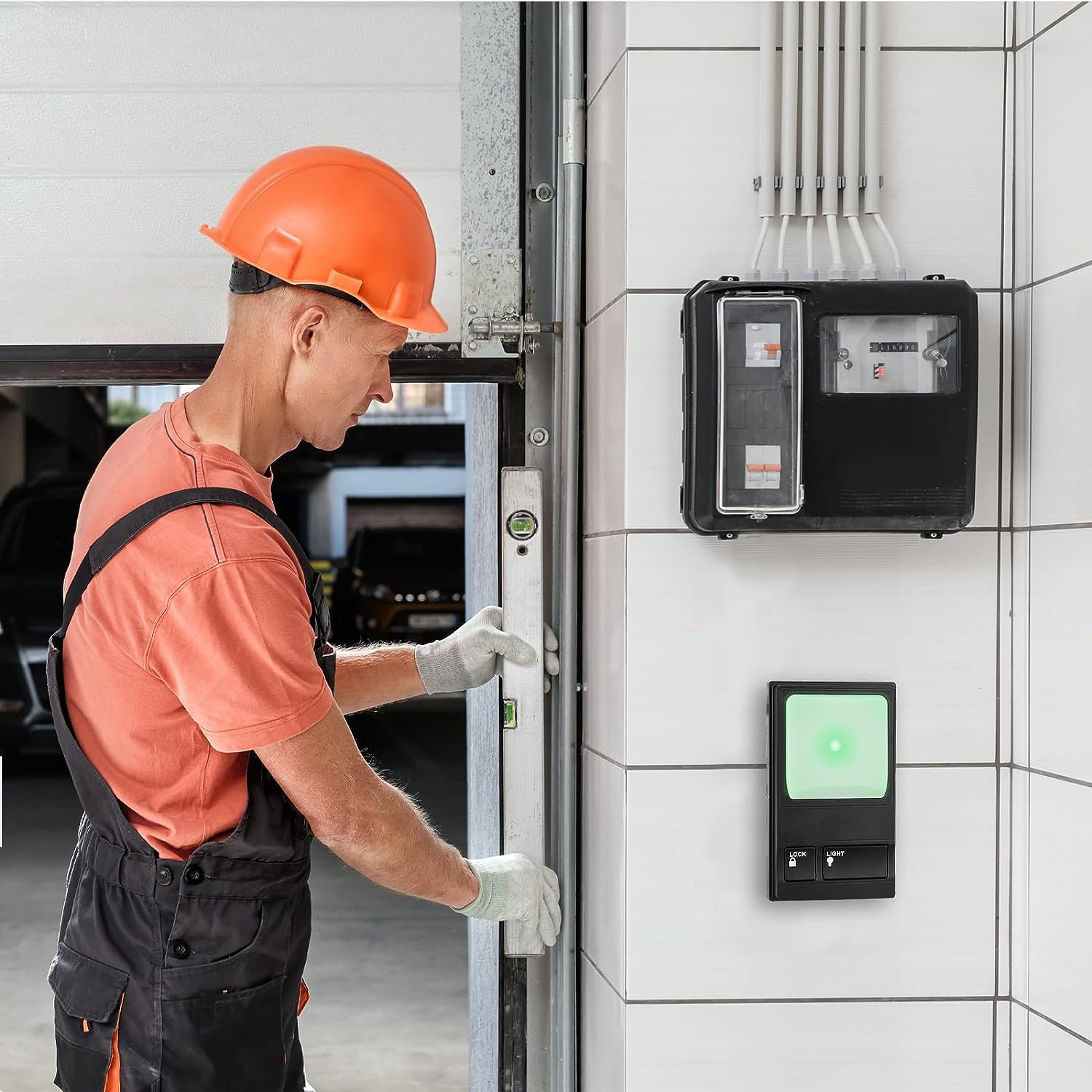
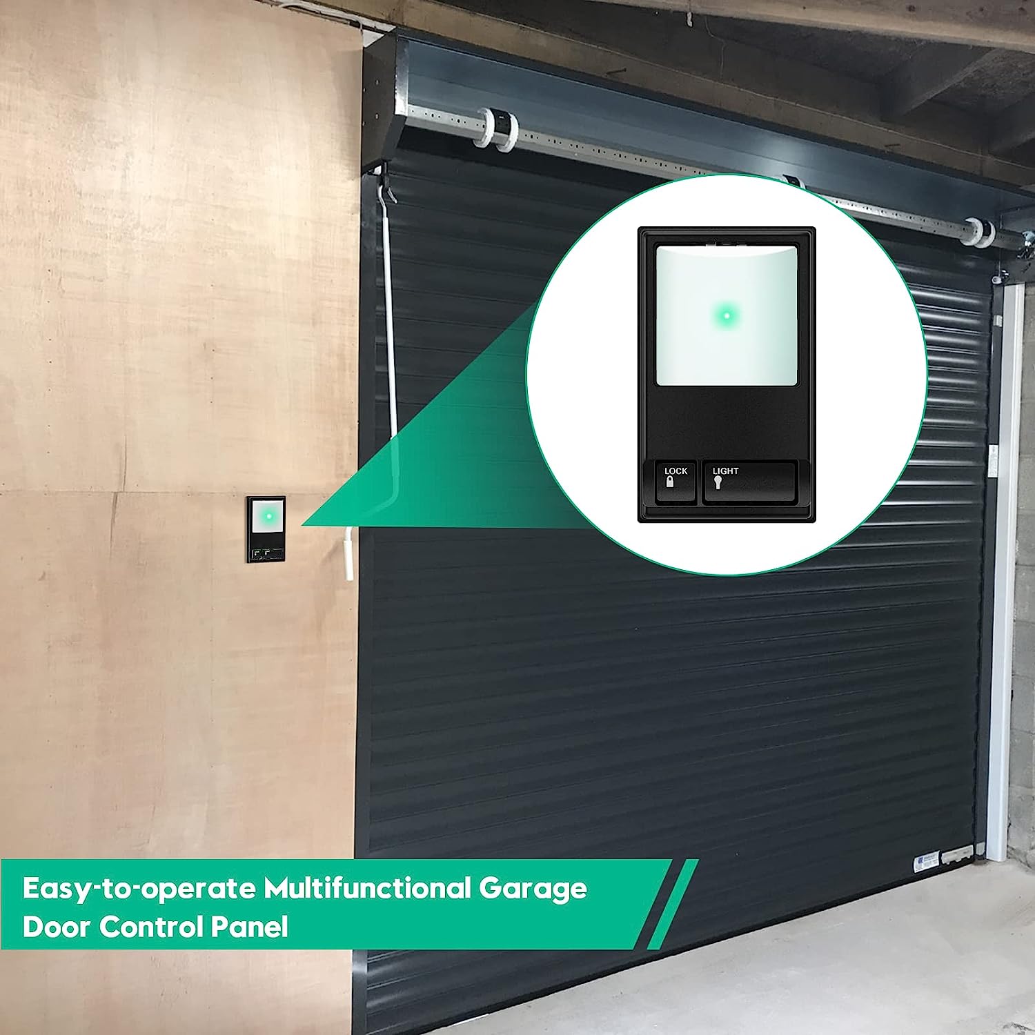
Indoor wall-mounted door controller, compatible with Security + systems.
Replaces standard door control buttons.
Conveniently installed in the garage through your access door,
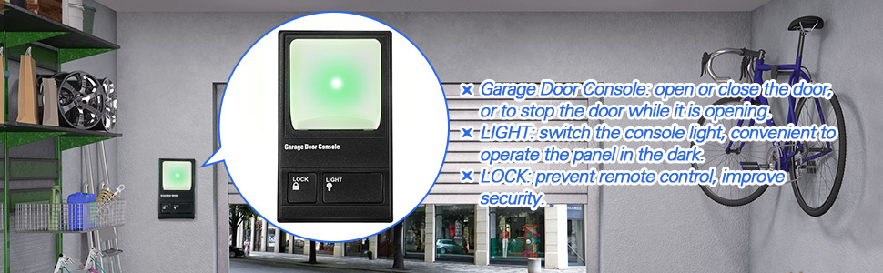
Open the garage door at the touch of a button.
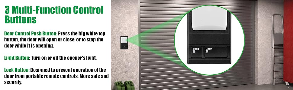
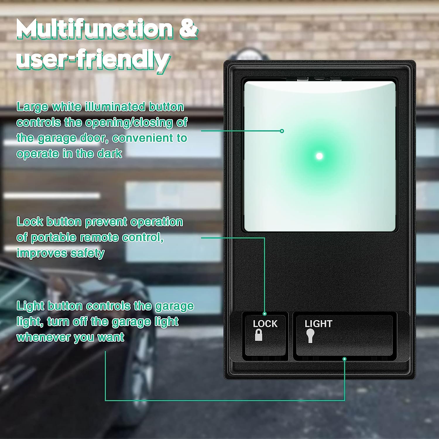
Includes an oversized illuminated push button.
Turn on and off opener lights to provide additional lighting for garage work.
Features that lock all external radio signals for added security.
All Security+ systems for LiftMaster (code rotation).
Also compatible with Chamberlain, Sears, Master Mechanic, Garage Master, Wayne-Dalton and Raynor.
For 78LM 79LM 81LM 371LM 971LM

Installation
1. Disconnect power to the garage door opener.
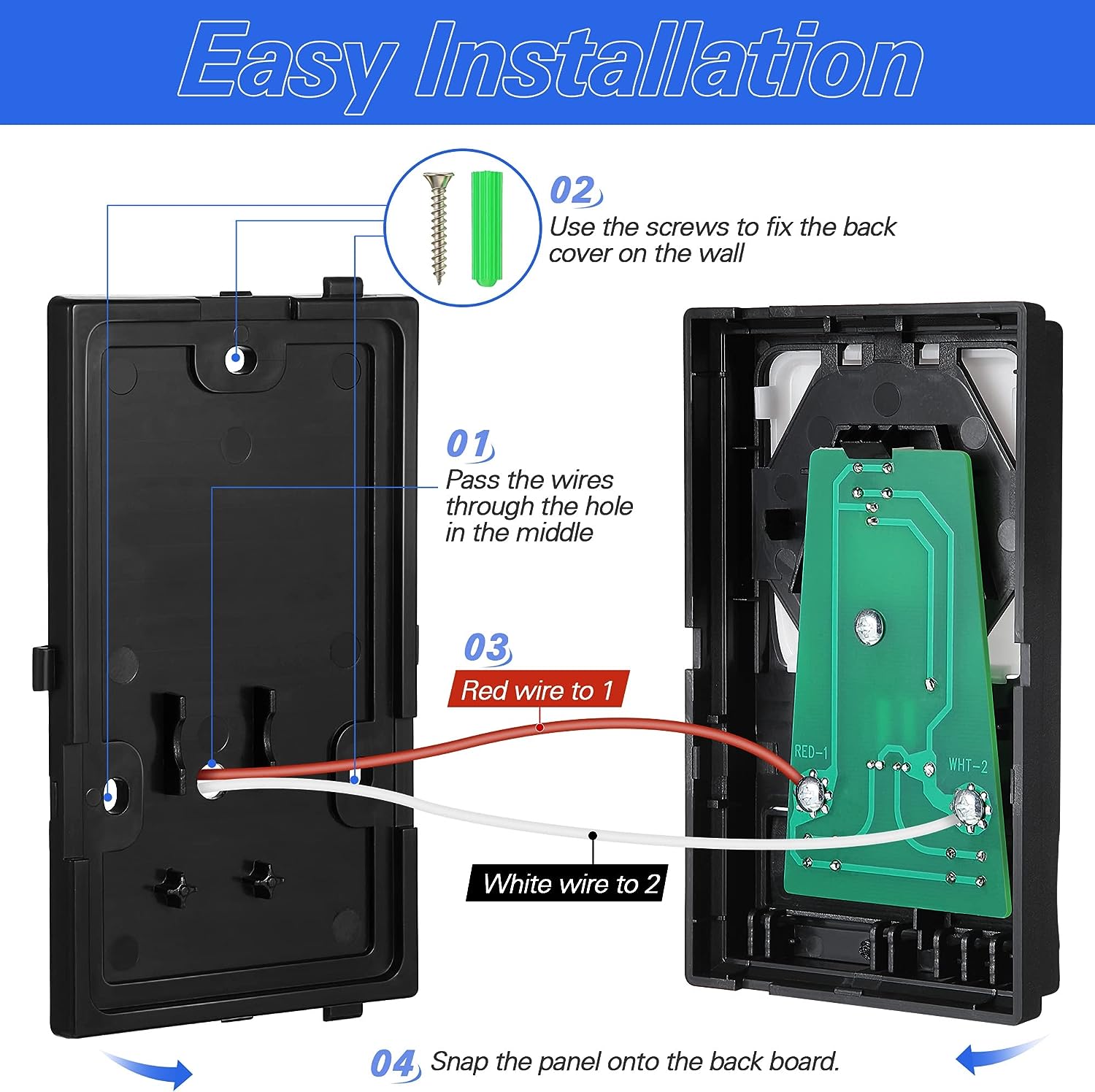
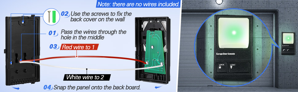
2. Strip ¼” (6 mm) of insulation from each end of wire. Pass the wires through ④ places.
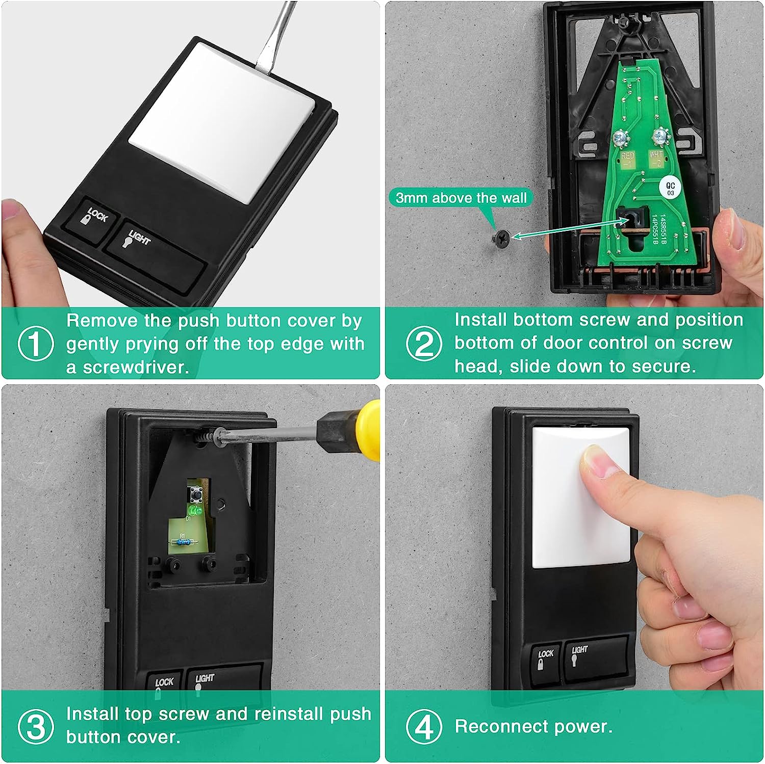
3. Use the included screws to fix the back cover on the wall nails.Fixed①,②,③ places. (Do Not overtighten,you may damage the plastic housing.)
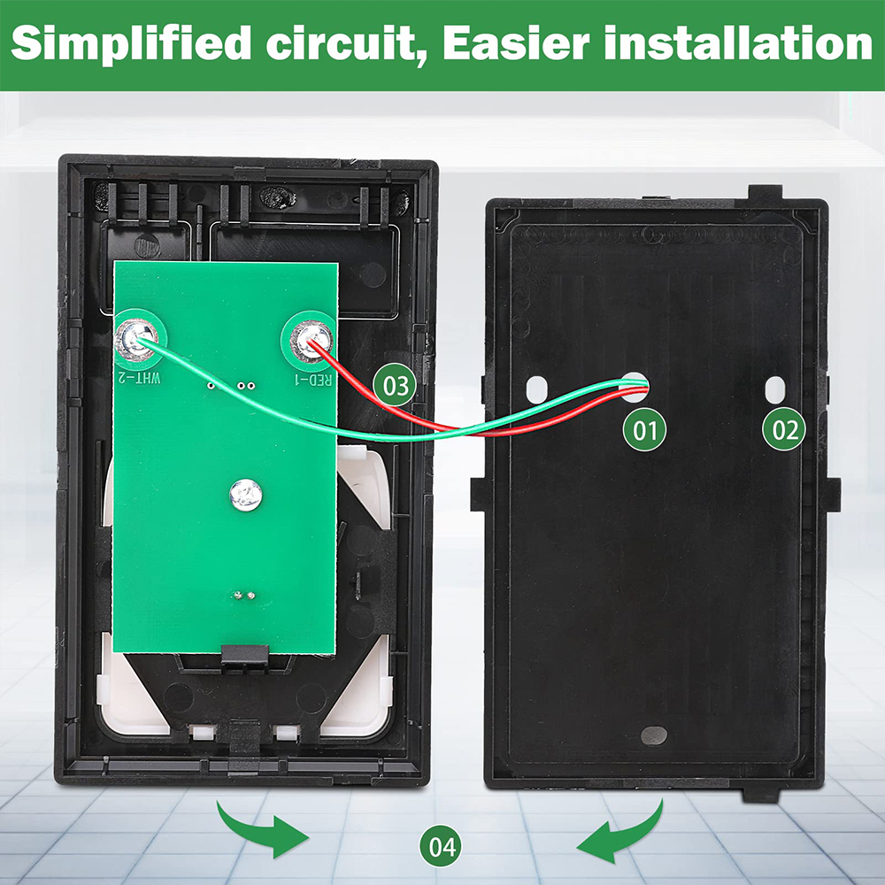
4. The wires passing through hole 4 are connected to the two screw terminals on the Circuit board as shown below:Red/white wire to 1 and white wire to 2 WOTE: After installation, the indicator light behind the push button cover will indicate proper connection.
5. Run bell wire up wall and across ceiling to motor unit. Use insulated staples to secure wire to wall and ceiling in several places. Do NOT pierce wire wit h a staple, this will create a short or open circuit.
6. Strip 7/16" 11 mm of insulation from the end of the bell wire
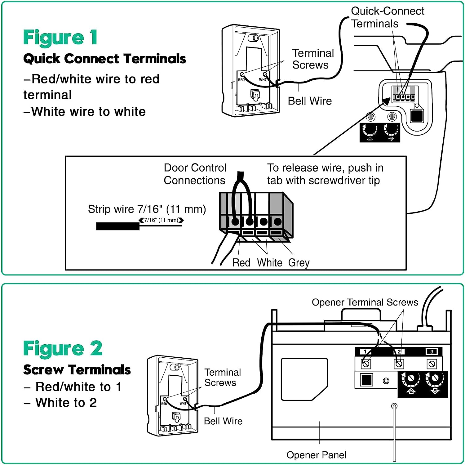
7. Connect bell wire to terminals as follows:
Quick Connect Term
Screw Terminals:Red/white to 1 and white 2(Figure 2).
8. Buckle the circuit board to the back cover.
9. Reconnect power to the garage door opener.
