Remove
- Move the vehicle to a 2 post lift. See Raise Vehicle - 2 Post Lift.
- Remove the HEPA filter inlet duct. See Duct - HEPA Filter - Inlet (Remove and Replace).
- Remove the HEPA filter outlet duct. See Duct - HEPA Filter - Outlet (Remove and Replace).
- Disconnect 12V power. See Disconnect 12V Power.
- Raise the vehicle to service under the HV battery.
- Remove all items from pockets and make sure not to wear any metal items.
- Inspect the HV insulating gloves.

- Put on the HV insulating gloves and the leather over gloves.

- Put on the HV-safe static control wrist strap. Clip the strap's ground connection to a threaded hole on the edge of the HV battery enclosure.
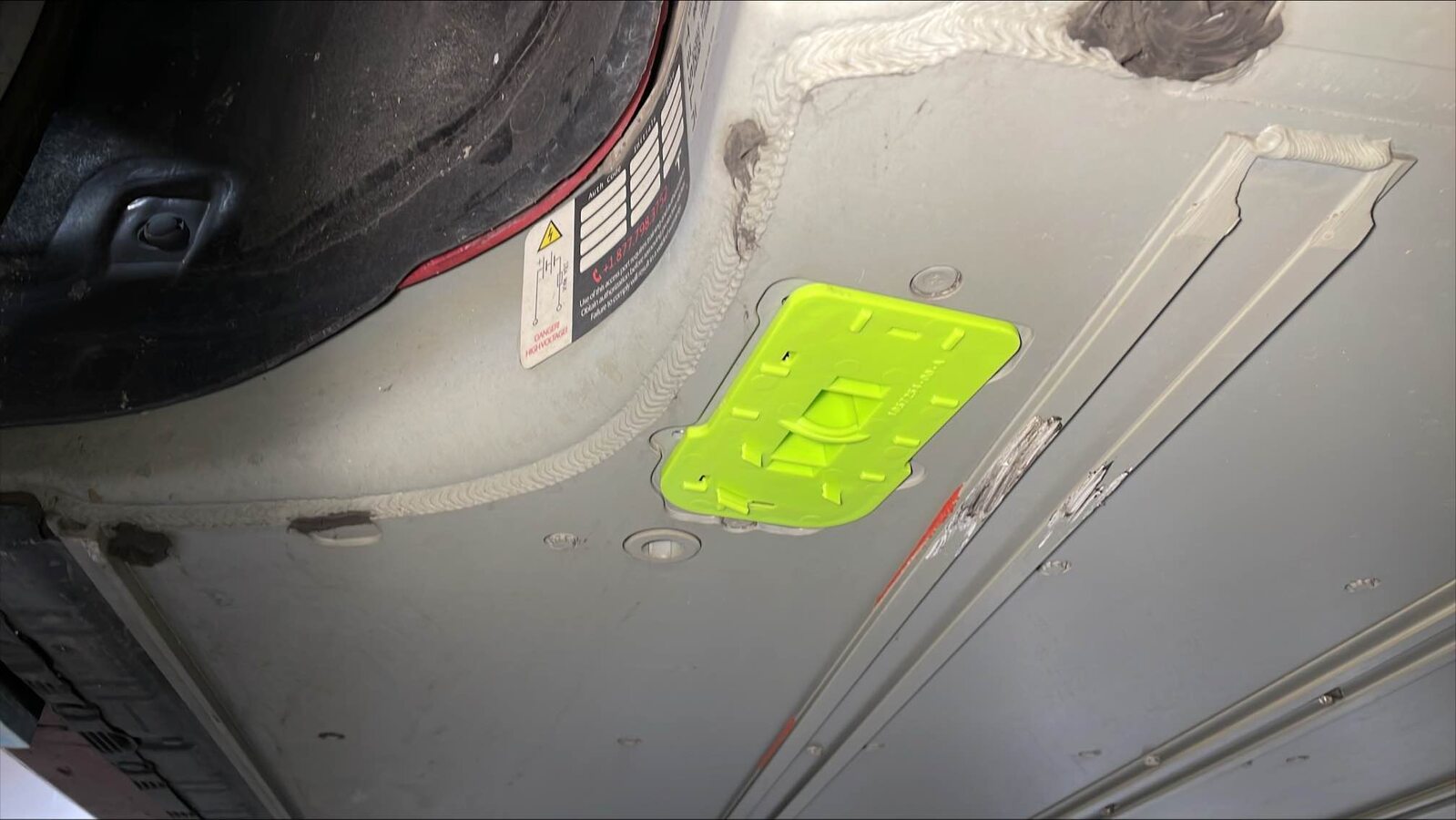
- Clean the area around the fuse cover with alcohol wipes.
- Remove the bolts (x6) that attach the fuse cover to the HV battery.
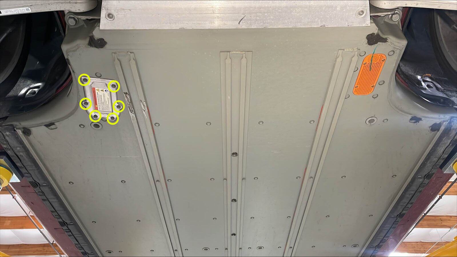
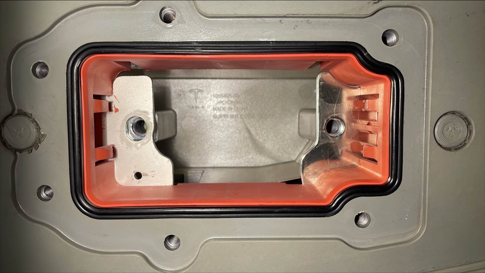
- Release the tabs (x2) that attach the fuse access cover to the fuse cavity, and then remove the cover from the cavity.
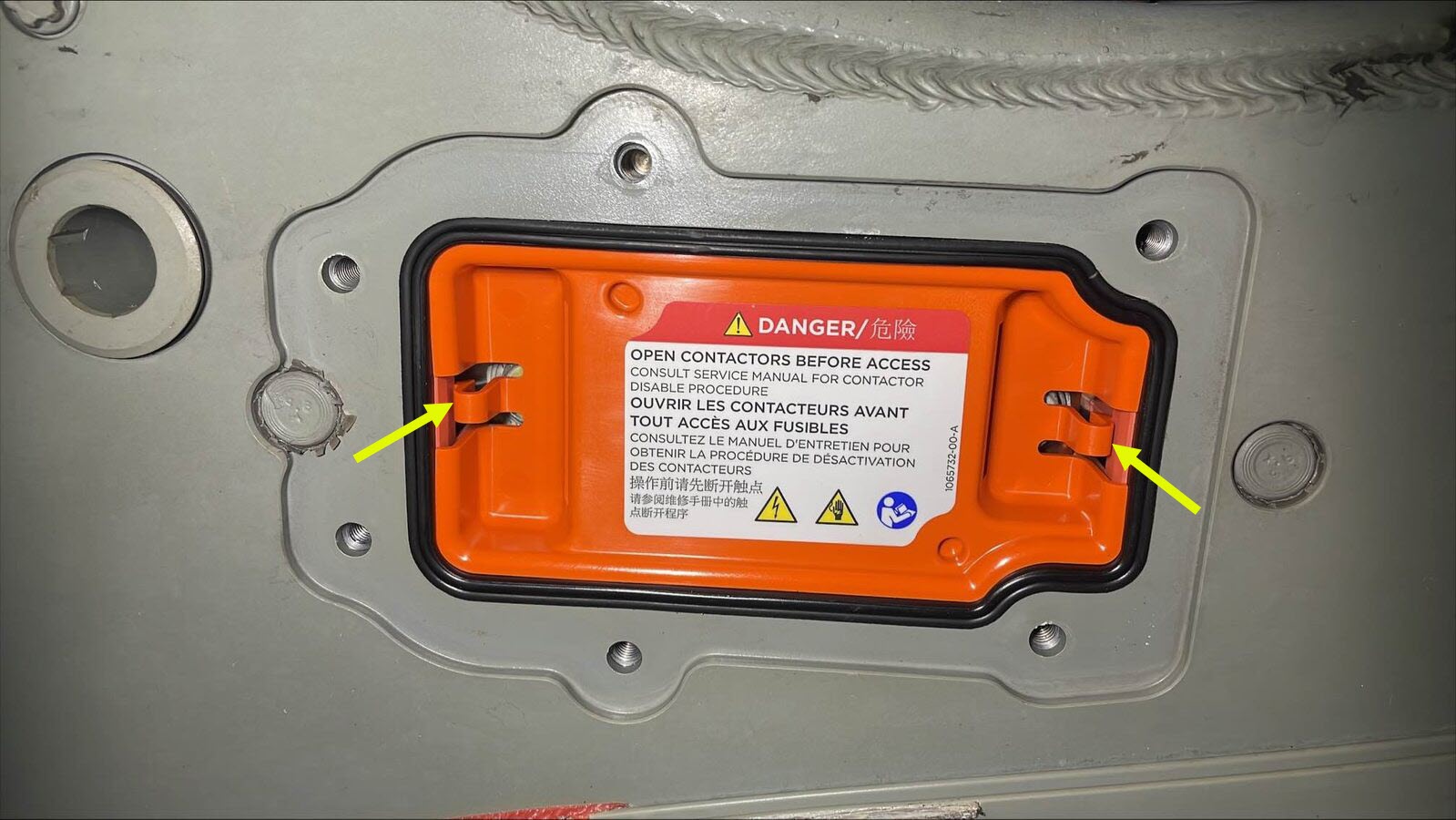
- Visually inspect the fuse cavity for water, dirt, evidence of arcing, or any other kind of damage. If any damage is found, escalate a Toolbox session, as appropriate.
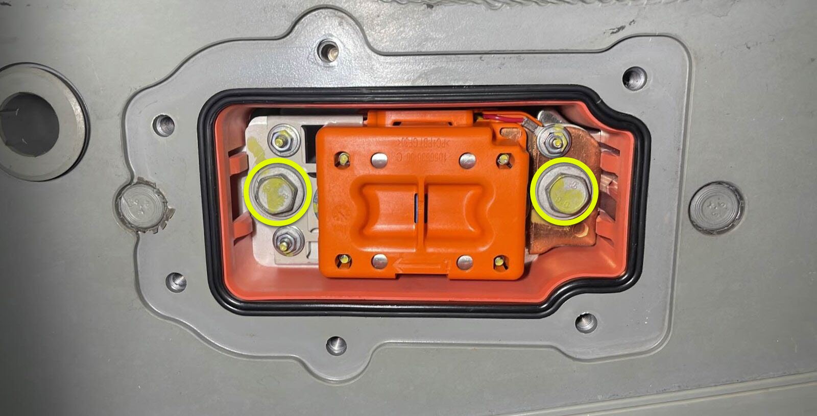
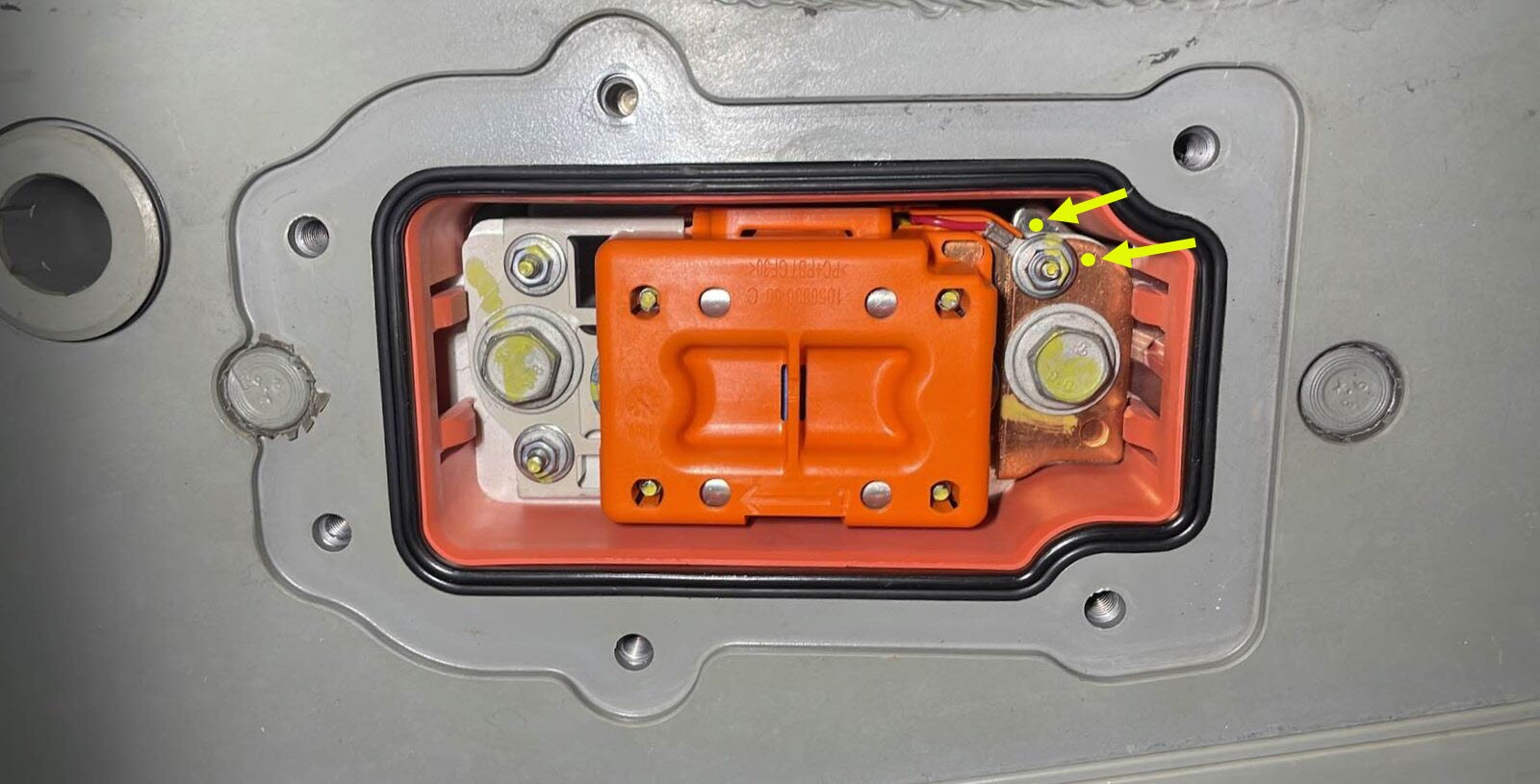
- Remove the bolts (x2) that attach the hybrid pyro fuse to the busbars.
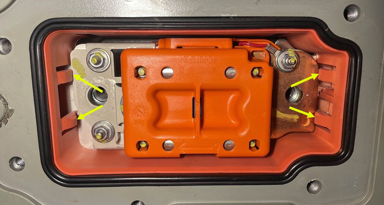
- Release the tabs (x4) that retain the hybrid pyro fuse within the fuse cavity, and then carefully remove the fuse from the cavity.
- Inspect the fuse cavity and cover area for rust or corrosion, and if any is found, refer to Toolbox article #3207900 for further guidance.
- Visually inspect the hybrid pyro fuse and the busbars within the fuse cavity for evidence of arcing. If there is any evidence of arcing, escalate the Toolbox session, as appropriate.
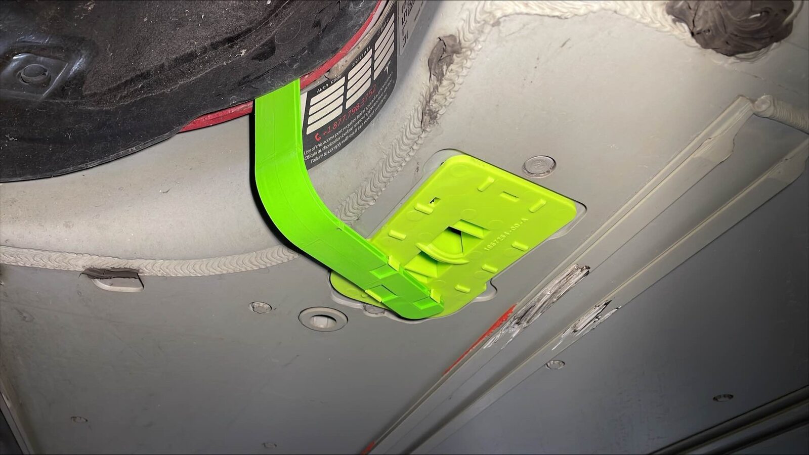
- Install the green fuse flag assembly to the fuse cavity.
- Record the part number and serial number on the fuse.
- Use this table to determine the type of fuse and action to take.
Part Number Fuse Type Action 1056211-00-* Battery Powered 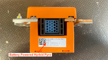
Replace with self-powered fuse 1077177-00-* 1086649-00-* 1112479-00-* 1112553-00-* 1111445-00-* Self-Powered 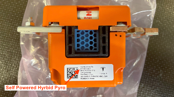
Reinstall fuse and ensure gateway configuration 1111313-00-* 1090924-00-* Various part numbers Sand Fuse 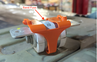
Reinstall fuse and ensure gateway configuration
Install
- Consider the action to take for the type of fuse removed.
- Battery Powered Hybrid Pyro Fuse - Install a Self-Powered Hybrid Pyro Fuse. See Fuse - Pyrotechnic - HV Battery 2.0 (Remove and Replace)
- Self-Powered Hybrid Pyro Fuse - Reinstall the fuse removed, go to step 2.
- Sand Fuse - Reinstall the fuse removed, go to step 2.
- Perform a zero adjust of the Hioki resistance meter in prepartion to measure resistances later in this procedure. See Resistance Meter (Zero Adjust).
- Remove the green fuse flag assembly.
- Use an IPA wipe to thoroughly clean the busbars within the fuse cavity and the terminals of the hybrid pyro fuse and allow at least 1 minute to dry.
- Position the hybrid pyro fuse with the embossed arrow pointing rearward, and then install the fuse into the fuse cavity past the tabs (x4) that retain the fuse.
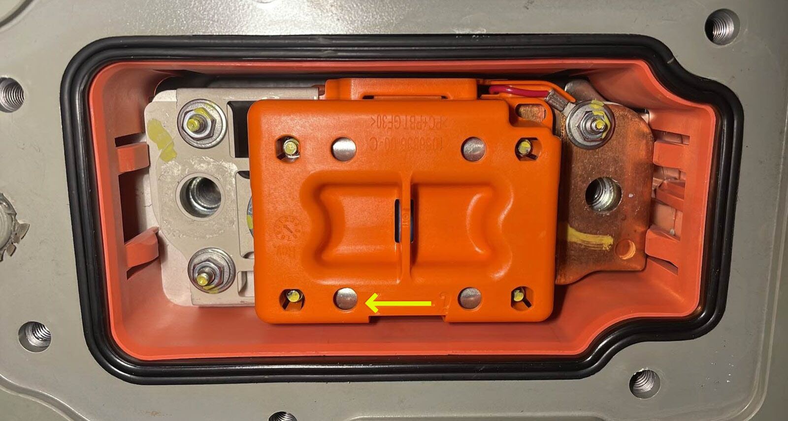
- Install the bolts (x2) that attach the hybrid pyro fuse to the busbars, and then mark the bolts with a paint pen after tightening.
 9 Nm (6.6 lbs-ft)
 - Use the Hioki resistance meter to meassure the resistance at the HV joint of the hybrid pyro fuse dull terminal and the dull busbar.
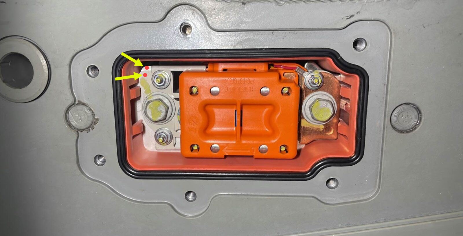
- Use the Hioki resistance meter to meassure the resistance at the HV joint of the hybrid pyro fuse copper terminal and the shiny busbar.
- Install the fuse access cover to the fuse cavity, and then fasten the tabs (x2) that attach the cover to the cavity.
- Use an IPA wipe to clean the sealing surface and gasket of the fuse cavity, the sealing surface of the fuse cover, and allow at least 1 minute to dry.

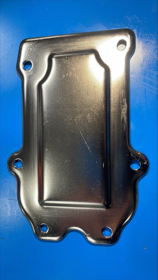
- Install the fuse cover to the HV battery, install the bolts (x6) that attach the fuse cover to the HV battery, and then mark the bolts with a paint pen after tightening.10 Nm (7.4 lbs-ft)
- Remove the leather glove protectors and the HV insulating gloves.

- Connect 12V power. See Disconnect 12V Power.
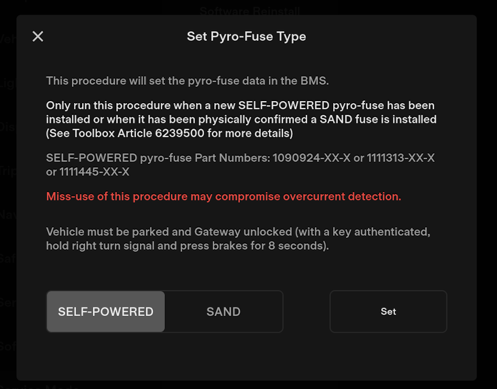
- If the vehicle is configured with a Tegra MCU, perform these substeps:
- Touch SELF-POWERED or SAND, as determined previously, touch Set, and allow the routine to complete.
- Touch SELF-POWERED or SAND, as determined previously, touch Set, and allow the routine to complete.
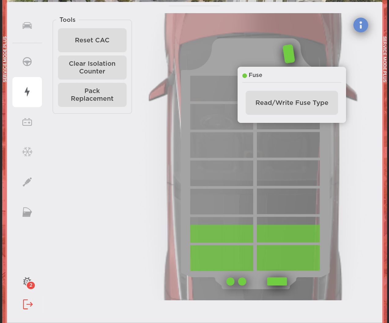
- If the vehicle is configured with an Intel MCU, perform these substeps:
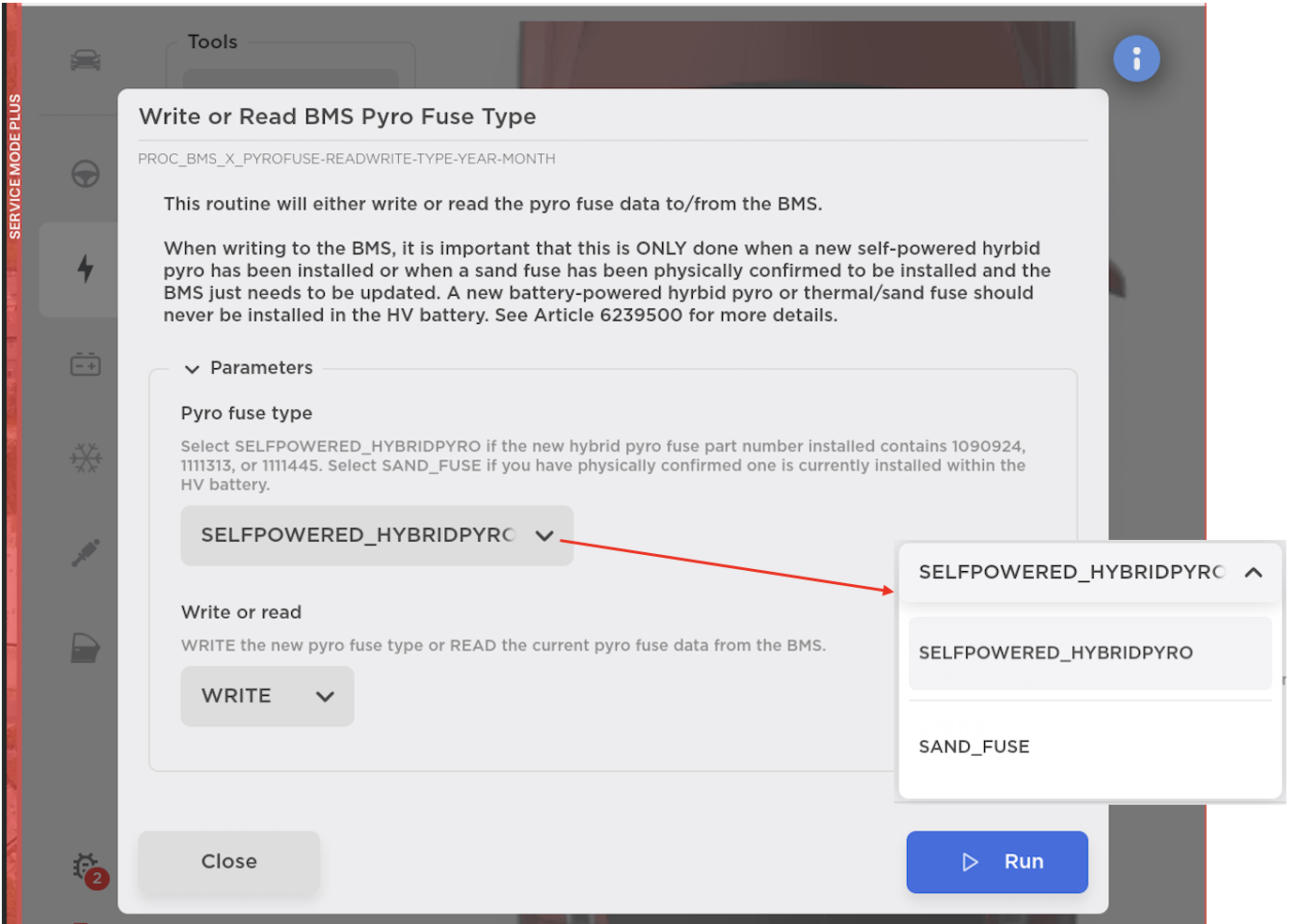
- On the vehicle touchscreen, touch HV Battery (Lightning Bolt), touch the green fuse in the graphic, touch Read/Write Fuse Type, and then read the instructions.
- From the Pyro fuse type drop down menu, select either SELFPOWERED_HYBRIDPYRO or SAND_FUSE, as determined previously, from the Write or read drop down menu, select WRITE, touch Run, and allow the routine to complete.
- On the vehicle touchscreen, touch HV Battery (Lightning Bolt), touch the green fuse in the graphic, touch Read/Write Fuse Type, and then read the instructions.
- Install the HEPA filter outlet duct. See Duct - HEPA Filter - Outlet (Remove and Replace).
- Install the HEPA filter inlet duct. See Duct - HEPA Filter - Inlet (Remove and Replace).
- Remove the vehicle from the 2 post lift. See Raise Vehicle - 2 Post Lift.