
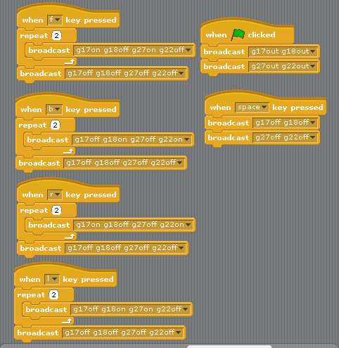
2 Motor control demo code forward, backward, turn right, turn left. stop
define GPIO 17,18,27,22, as output
1.press keyboard " f " GPIO 17,27 LED "ON" & 18,22 LED "OFF" car move forward
2.press keyboard " b " GPIO 18,22 LED "ON" & 17,27 LED "OFF" car move backward
3.press keyboard " l " GPIO 18,27 LED "ON" & 17,22 LED "OFF" car turn right
4.press keyboard " r " GPIO 17,22 LED "ON" & 18,27 LED "OFF" car turn left
5.press keyboard " space " GPIO 17,27 LED "OFF" & 18,22 LED "OFF" car STOP
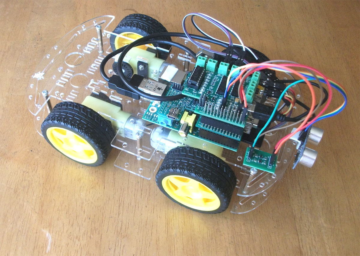
4 x DC 5V motor 1 x ultrasonic module 1x WiFi USB dongle
1x Bluetooth USB dongle 1x 2 channel Level Converter
1 x Raspberry Pi type B- V2 512MB
1x RS-Pi- 4USB hub Board
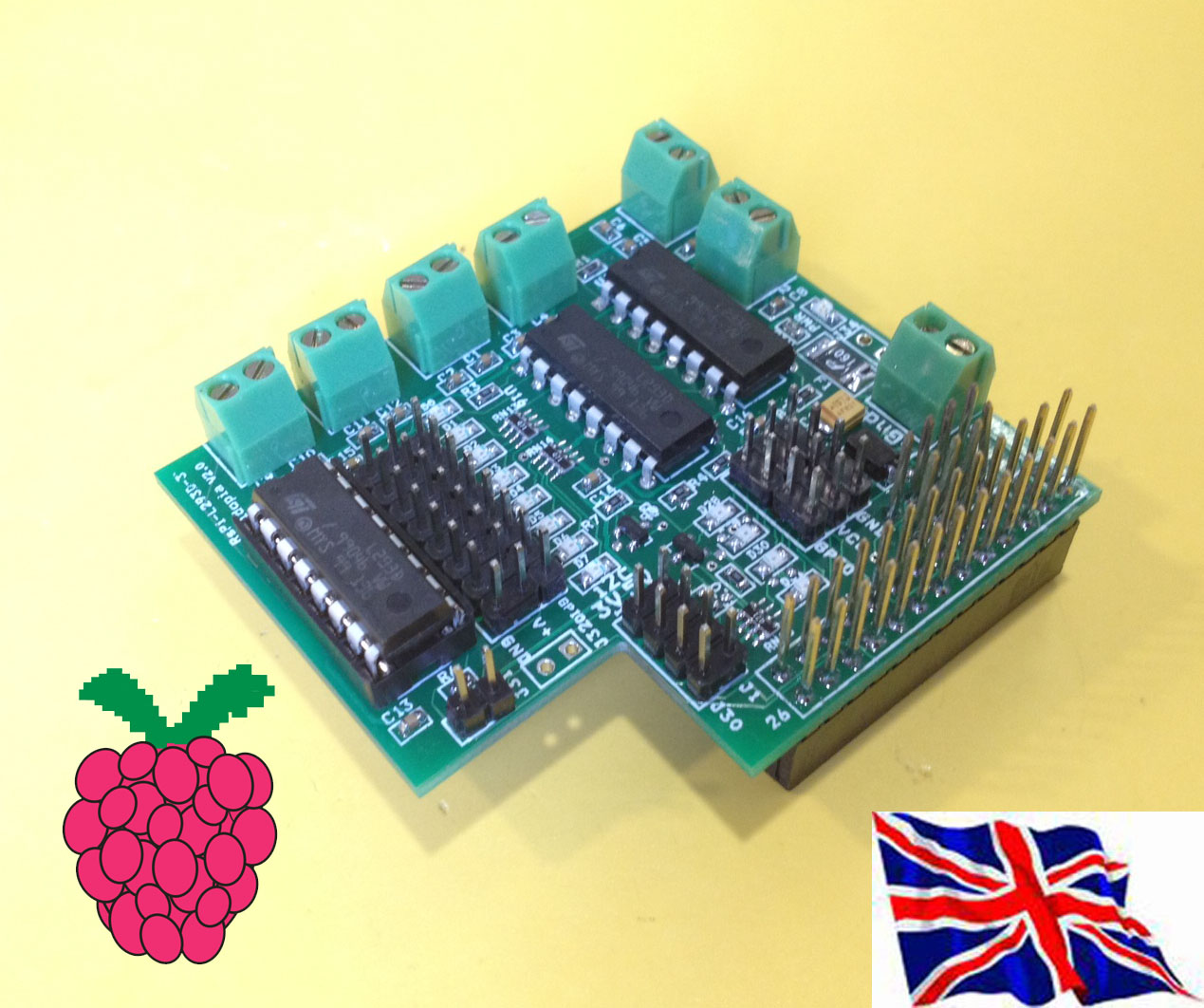
1x Rs-Pi-L293D-3 Motor Board
1. Change Maplin Robot Arm from PC base, USB port to Raspberry Pi Base,
GPIO Motor Control,
2. remove Battery use 12V DC power adapter for Raspberry Pi and Robot Arm.
Use 1.Rs-pi–L293D-3 6 Motor Board -
Control Robot Arm 5 Motor (M1,M2,M3,M4,M5)
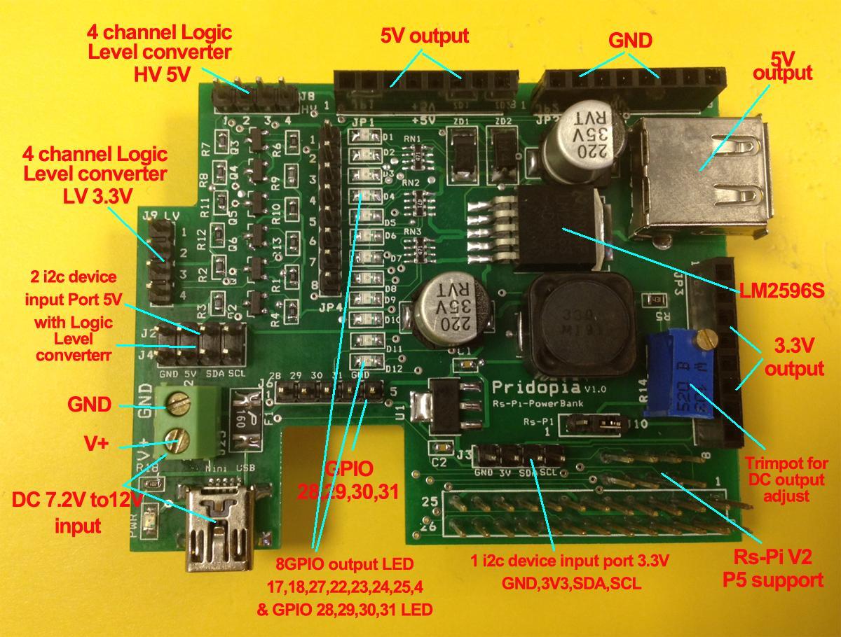
2.Rs-Pi-Power Bank Multi-function Board
Use DC12V adapter, provide Raspberry Pi 5V and
all the power for Robot Arm & 5 DC Motor

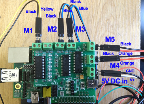
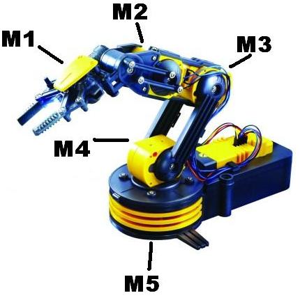
(1) xWindow control mode Maplin-Arm.py use keyboard and Mouse control
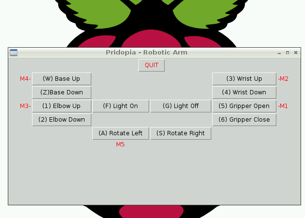
(2)Scratch GPIO control mode
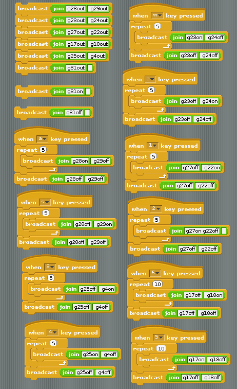
1. setting GPIO 17,18,27,22,23,24,25,4 as output
2. setting GPIO 28,29,31 as output
a KEY GPIO 28,29 M1 CLOCKWISE
s KEY GPIO 28,29 M1 ANTICLOCKWISE
w KEY GPIO 23,24 M2 CLOCKWISE
z KEY GPIO 23,24 M2 ANTICLOCKWISE
1 KEY GPIO 27,22 M4 CLOCKWISE
2 KEY GPIO 27,22 M4 ANTICLOCKWISE
3 KEY GPIO 25,4 M3 CLOCKWISE
4 KEY GPIO 25,4 M3 ANTICLOCKWISE
5 KEY GPIO 17,18 M5 CLOCKWISE
6 KEY GPIO 17,18 M5 ANTICLOCKWISE
(3)Scratch PWM command mode
A - GPIO 17,18 Motor A B - GPIO 27,22 Motor B
C - GPIO 23,24 Motor C D - GPIO 25,4 Motor D
E - GPIO 28,29 Motor E
command "Motor Name"+ "DM"+"speed"
speed (10 ~100) clockwise
speed (-10 ~ -100) anticlockwise

Perfect way to learn how to use the GPIO pins.
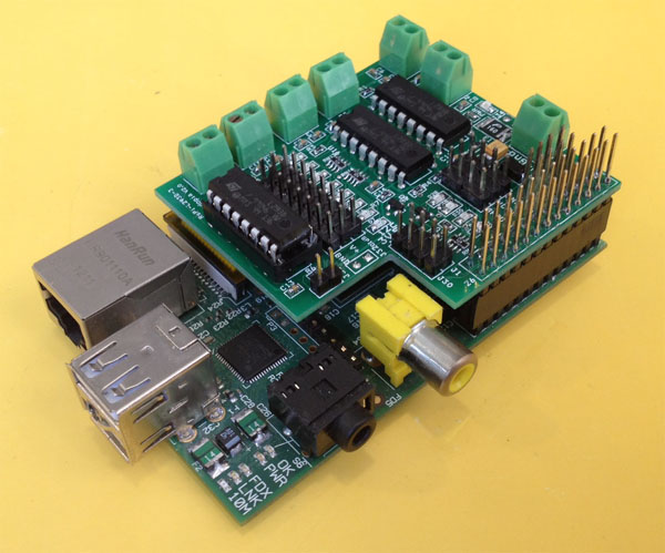
Plugs into the Raspberry Pi GPIO connector.
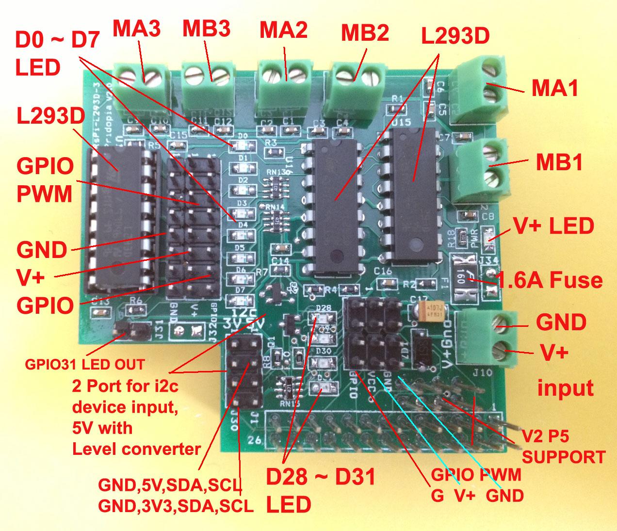
Has eight Blue LED's and controls up to 4 DC motors,
extra 4 Blue LED (GPIO 28,29,30,31) for another 2 Motor
or ultrasonic sensor or other devices
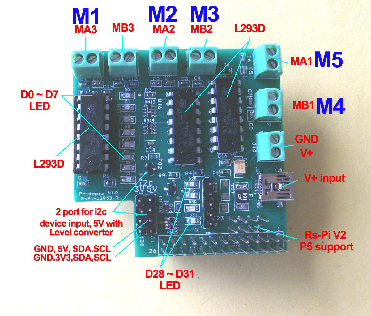
This board use RS-Pi pin 11,12,13,15,16,18,22,7 as GPIO 0 to GPIO7 * GPIO 0 ~ 3 for MA1, MB1
* GPIO 4 ~ 7 for MA2, MB2
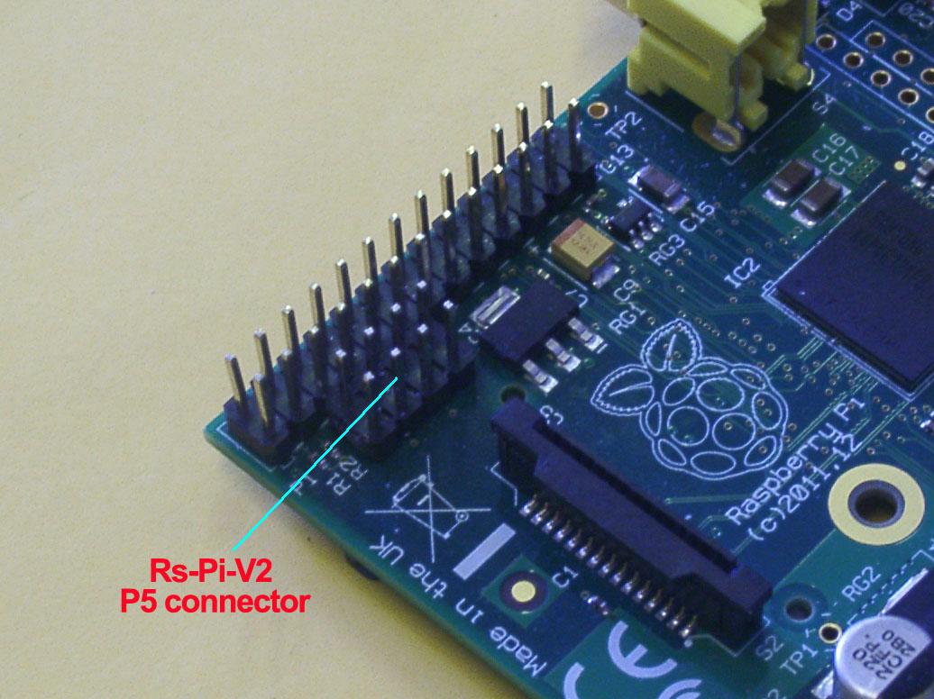
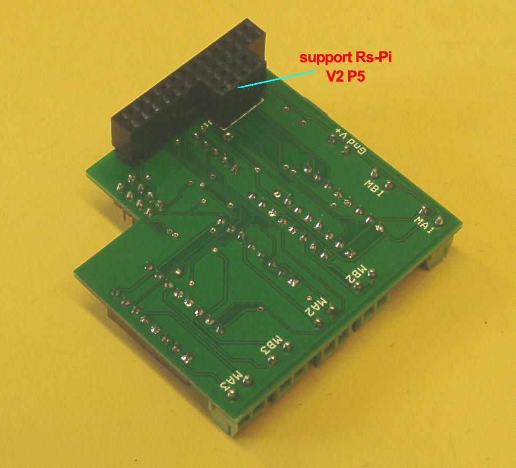
* GPIO 28 ~31 for MA3,MB3 (need V2 - P5 connector) or use for ultrasonic sensor connector (2GPIO , one for Trig, one for Echo)
2 extra 12c input for sensors (5V or 3v3) (5V port with Level converter)
* J30 3V3 i2c device input (GND, 3V3, SDA,SCL)
.* J1 5V i2c output (GND,5V,SDA,SCL) ( with Logic Level Converter)
* J7 Mini USB 5V input or J10(2p terminal Block)
Use this board you can learn how to program use "C" or "Python" ,
provide 3 python pprogram for test can be download from our web site.
2motor.py 4motor.py 6 motor.py
Package Content
1x Rs-Pi L293D-3 6 Motor - Board
1x Manual
Raspberry Pi® is a trademark of the Raspberry Pi Foundation
Payment1.We accept payment through Paypal ONLY.
2. We ship your orders within 1-2 business days after the payment cleared.
3. We ship to address provided by PAYPAL only.
4. Our standard shipping method is from United Kingdom by Royal Mail First Class Record & Royal Mail International Sign For.
5. Usually Delivery Time approximately 1 - 2 business days, In rare cases,it may take longer due to delay in holidays.
6. If your item does not arrive within 7 days please get in contact with us.
7. Our working day from Monday to Friday, 10am to 4pm