


Pierburg CWA150 Brushless Water Pump 20mm OD - 12v
The Pierburg Electrical CWA coolant pumps make a significant contribution to emission control on modern engine designs. A delivery rate that is not dependent on the speed of another drive enables demand-based cooling. This reduces the power requirements whilst also cutting down on frictional loss, fuel consumption and pollutant emissions.
Electrical CWA coolant pumps offer top performance. They can be used for the main cooling of the combustion engine, as well as for cooling the fuel cell stacks of fuel cell drives.
Pierburg has made the electrical water pump ready for series production and was the world’s first series-production supplier for a leading premium vehicle manufacturer.
- Compact radial auxiliary coolant pump.
- Speed control and extended diagnostics information via PWM or LIN bus.
- Efficiency close to 40% at the nominal operating point.
- Demand-based cooling.
- High flow rate at a low pressure.
- Homogeneous heat dissipation.
- Optimised for high-temperature applications and more demanding service life requirements.
- Improved resistance to influences that impair EMC.
| Specification | Metric | Imperial & Other |
| Liquid Temp Range | -40 to 80 °C | -40 to 176 °F |
| Ambient Temp Range | -40 to 100 °C | -40 to 212 °F |
| Hose Size | Ø 20 mm | Ø 0.787" |
| Nominal Diff. Pressure | 1.4 Bar | 20.3 Psi |
| Weight | 1 kg | 2.2 lbs |
| Voltage | 12v | |
| Maximum Current Draw | 15a | |
| Maximum Electrical Consumption | 180w | |
| Protection | IP54 Rated | |
| Motor Type | Brushless Motor | |
| Conformity | Complies with Electromagnetic Compatibility Directive 2004/108/EC: (EN55014-1: 2006), (EN55014-2: 1997 +A1: 2001), (EN61000-6-3: 2007) (2004/104/EC: 2004 Annex1; paragraph 6.5, 6.6, 6.8 and 6.9) | |
| Manufacturer Part Number | 7.09578.00.0 | |


| Pin | Use | |
| 1 | Ground | |
| 2 | PWM Signal | |
| 3 | +12v |
Connector Part Numbers
| Part | Description | Part Number | Quantity |
| Plug (Male) | Kostal | 09441391 | 1 |
| Terminal | Kostal SLK 2.8 ELA | 22124499560 | 3 |
| Seal | Kostal SLK 2.8 ELA Seal | 10800444522 | 3 |
Plug, terminals and seals sold separately
Please ensure your supply is fused appropriately.
PWM Input Frequency
The PWM interface has the capability to handle frequencies between 50 to 500 Hz.
The chosen frequency will be automatically detected by the pump
The maximum deviation to the nominal frequency must not exceed 5%
Duty Cycle vs Speed

| Mode | Duty Cycle | Speed | Description |
| 1 | 0% - 5% | 6692 rpm | Emergency Run |
| 2 | 10% | 0 rpm | Stop |
| 3 | 15% - 95% | 222 - 6692 rpm | Controlled Operation |
| 3.1 | 15% - 22% | 222 - 803 rpm | Open Loop Mode |
| 3.2 | 23% - 95% | 886 - 6692 rpm | Closed Loop Mode |
| 4 | 98% - 100% | 6692 rpm | Emergency Run |
The tolerance of the pump's interpretation of the PWM signal can vary +/-2% of the duty cycle.
PWM Diagnostics
| Mode | Priority | Signal Type |
| Normal Mode | 1 | Low: 0.5s, High: 9.5s (Alive Signal) |
| Error Mode | Priority | Signal Type |
| Dry Run | 1 | Low: t=1.0s |
| Stall | 2 | Low: t=1.5s |
| Over Temperature | 3 | Low: t=2.0s |
| Speed / Power Reduction | 4 | Low: t=2.5s |
| No Alive Signal | 5 | - |
Duty Cycle
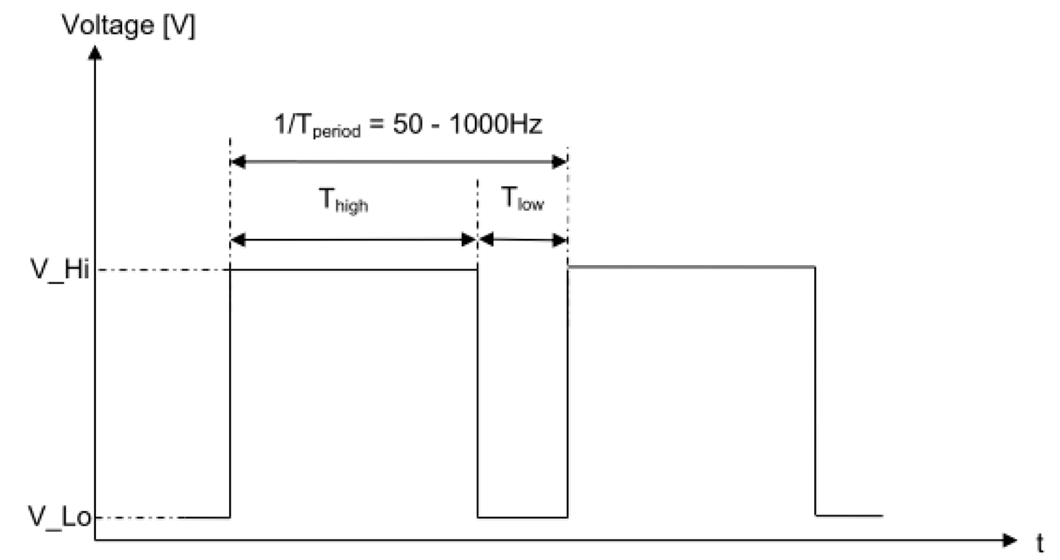
The percentage duty cycle is represented by the relationship of Thigh to TPeriod.
Duty cycle is PWM.
Duty Cycle %=Thigh / (Tlow + Thigh).


- The pump can be installed in either a horizontal or vertical position. To avoid air-locks when mounted horizontally, the outlet should be turned in such a way that it is directed upwards or is placed on the upper side of the pump body.