OMICRON CP SB1 Advanced 3-Phase Ratio & Winding Resistance Switch Box
The OMICRON CP SB1 Advanced is a CPC 100 accessory that expands three-phase power transformer testing with automated ratio measurement, winding resistance measurement, and tap changer control across phases and tap positions without phase rewiring.
Detailed Overview
Automated Three-Phase Transformer Testing with the OMICRON CP SB1
The OMICRON CP SB1 Advanced is a transformer switch box accessory for the CPC 100 test system. It addresses the time and connection complexity of testing three-phase power transformers by coordinating ratio measurement, winding resistance measurement, phase selection, and tap changer operation without repeated phase rewiring. The Advanced configuration adds licensed automatic tap-check operation for more complete testing across phases and tap positions.
Relay-Controlled Measurement Sequencing Across Phases and Taps
The internal relay switching matrix routes CPC 100 test signals through the selected transformer connections while serial control coordinates the measurement sequence. This arrangement reduces manual reconnection between phases and enables repeatable progression through supported transformer tests.
- Automatic phase switching without repeated phase rewiring
- CPC 100 serial control of relay and measurement sequencing
- Potential-free tap-up and tap-down contact operation
- Automatic transformer discharge during phase transitions
- Manual wiring mode for special measurements and single-phase transformers
Advanced Automation, Measurement Data, and Test Efficiency
The Advanced license expands automatic tap-check operation through the CPC 100 TRRatio and TRTapCheck procedures. Measurement results are recorded by the CPC 100 for evaluation, while supported templates and the CPC 100 Excel File Loader provide a defined path for post-processing and report generation.
- Automated testing across three phases and multiple tap positions
- Ratio, deviation, excitation current, and phase-angle measurement
- Winding resistance measurement with current up to 6 A DC
- Ripple and slope capture during tap changer transitions
- XML result transfer to corresponding Microsoft Excel templates
Power Transformer Field Testing and Deployment
The CP SB1 supports field workflows involving three-phase power transformer ratio, winding resistance, and on-load tap changer evaluation. A compact 14.1 × 9.2 × 4.4 in housing and 7.7 lb instrument weight support transport and placement within the designated test area.
- Transformer ratio measurement across individual tap positions
- High- or low-voltage winding resistance measurement
- On-load tap changer switching and interruption evaluation
Key Benefits
-
✓Fully Tested & Certified
-
✓30-Day Risk-Free Returns
-
✓1-Year Full Warranty
-
✓Professional Calibration Services
-
✓Trade-In Program Available
-
✓Fast & Reliable Delivery
What's in the Box
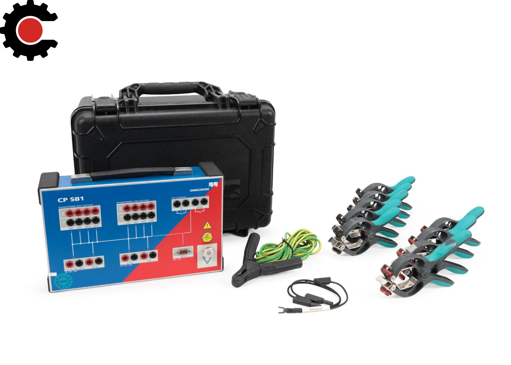
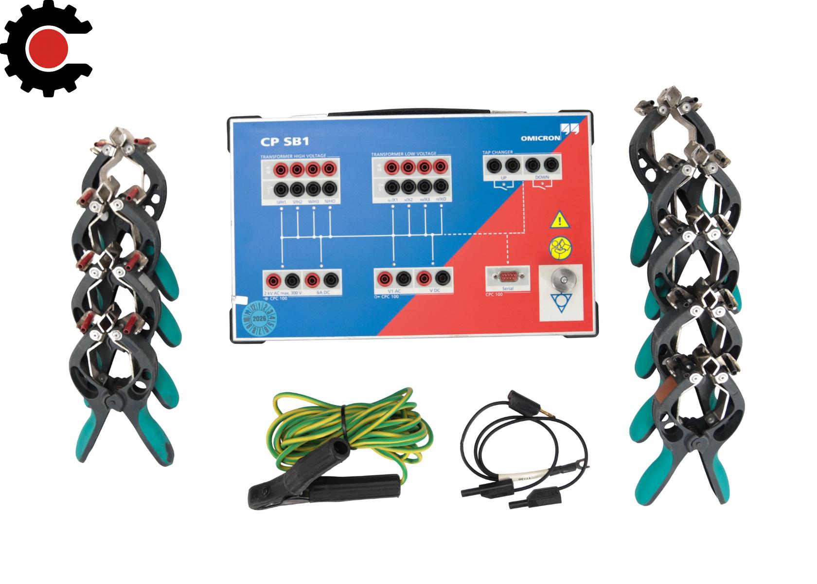
- 1 x OMICRON CP SB1 Advanced Switch Box
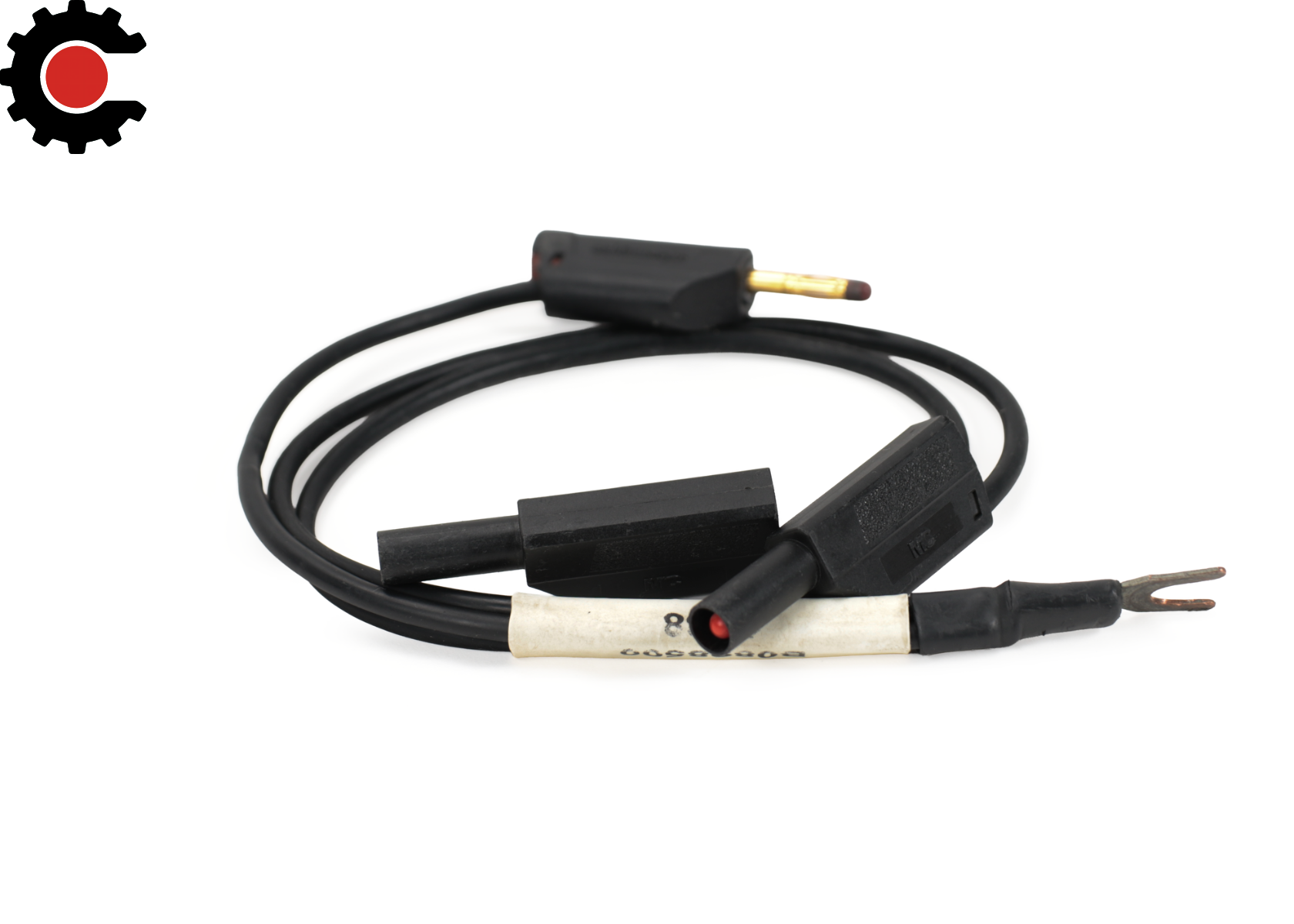
- 1 x OMICRON B0898500 Short-Circuit Strip Black 3 Pole 0.3 m 1 mm²
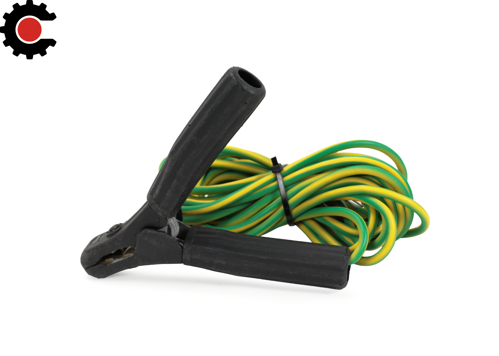
- 1 x OMICRON B0349701 Ground Cable 6 m YE/GN 1p 6 mm² Si
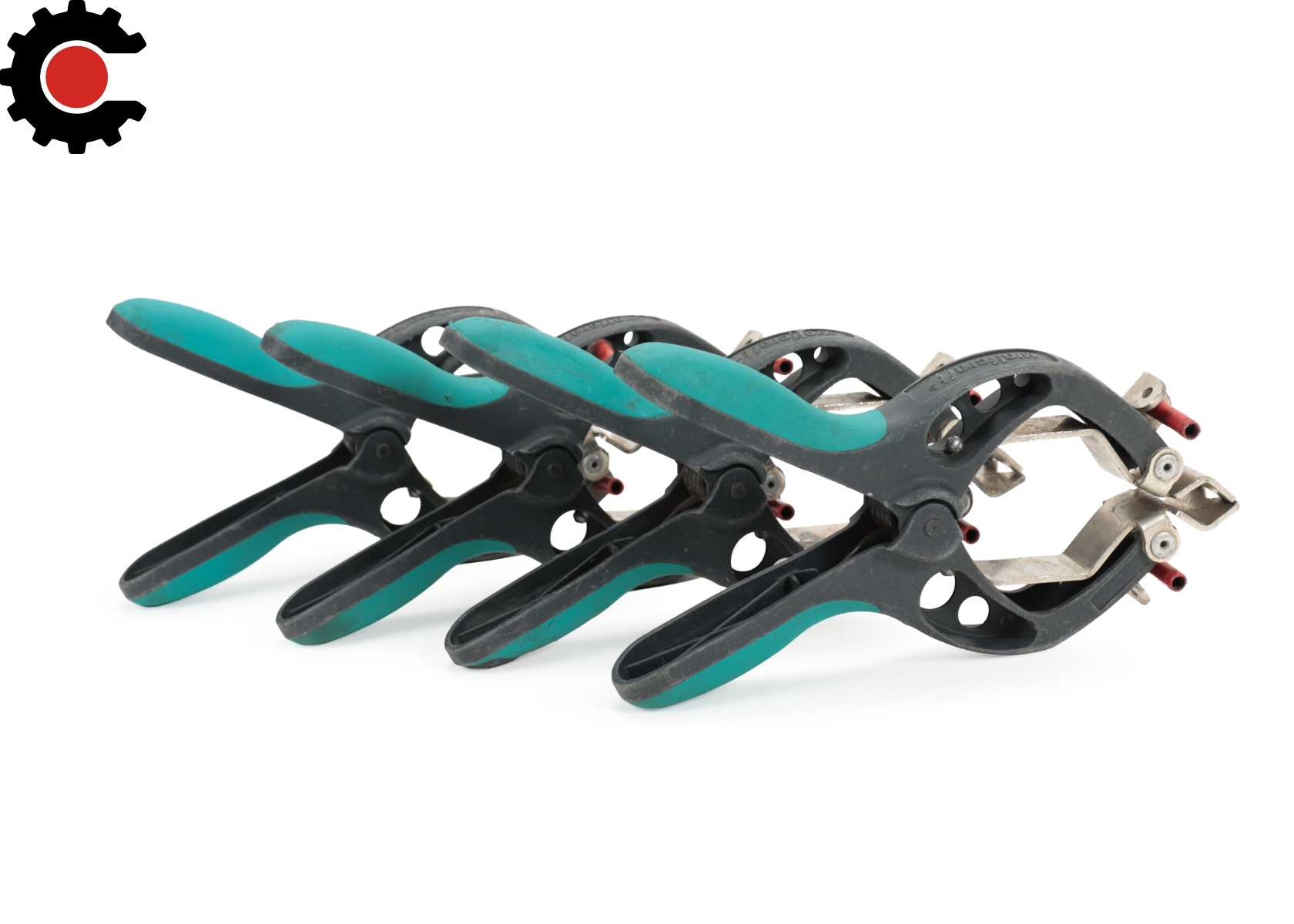
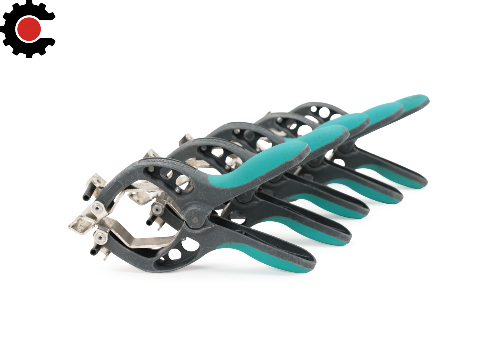
- 5 x OMICRON B0508900 Kelvin Clamp Black FZ60-BU-BLK CP
- 4 x OMICRON B0508901 Kelvin Clamp Red FZ60-BU-RED CP
- 1 x Hard Transport Case
Technical Specifications
| Product Identification | |
|---|---|
| Model | CP SB1 |
| Product Type | Transformer Switch Box |
| Supported Test System | OMICRON CPC 100 V1 |
| Primary Test Object | Three-phase power transformers |
| Measurement Functions | |
| Transformer Ratio Measurement | Supported with the CPC 100 TRRatio test card |
| Winding Resistance Measurement | Supported with the CPC 100 TRTapCheck test card |
| Tap Changer Testing | Winding resistance and on-load tap changer interruption evaluation |
| Measurement Phases | Three phases |
| Transformer Ratio Test Voltage | Up to 300 V for Y and D transformers; up to 150 V for YN transformers |
| Winding Resistance Test Current | Up to 6 A DC |
| Ratio Measurement Values | Primary voltage, secondary voltage, calculated ratio, ratio deviation, excitation current, and phase angle |
| Tap Changer Test Values | Measured resistance, resistance deviation, temperature-corrected resistance, ripple, and slope |
| Transformer Connections | |
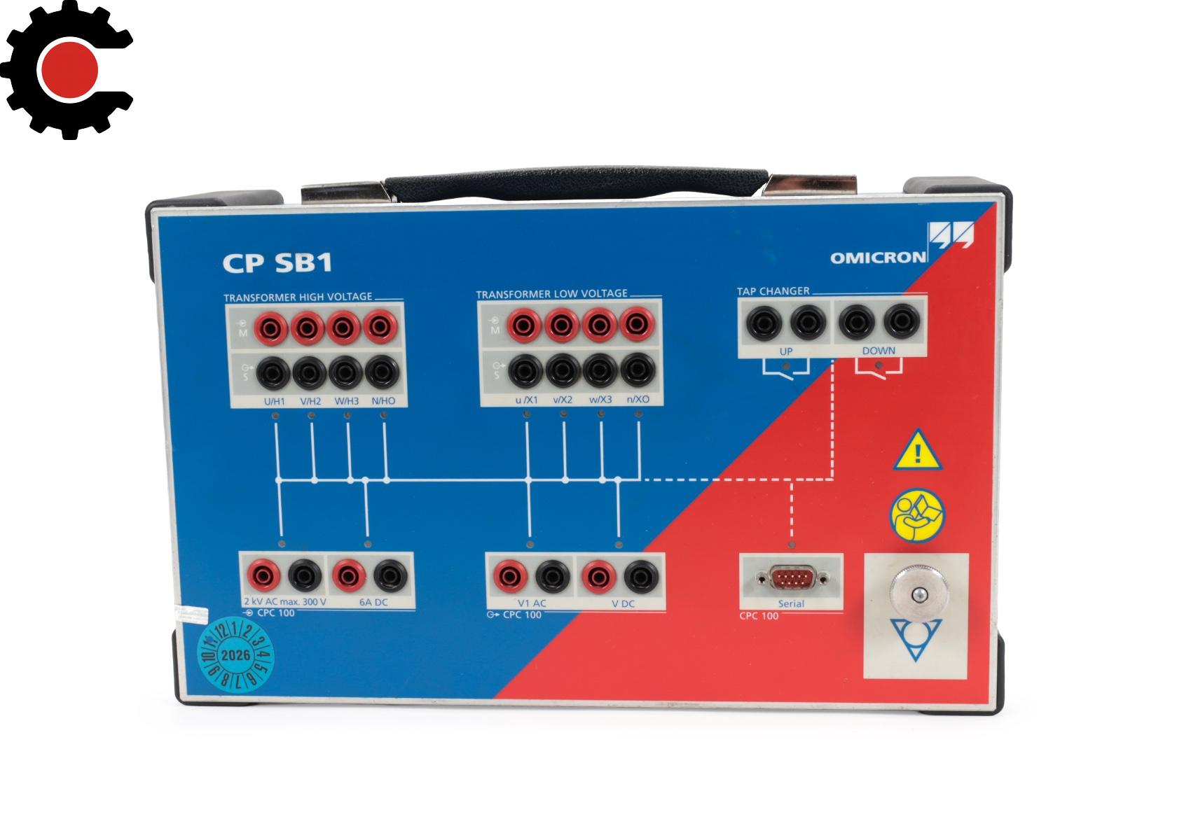
| High-Voltage Transformer Terminals | U/H1, V/H2, W/H3, and N/H0 source and measurement connections |
| Low-Voltage Transformer Terminals | u/X1, v/X2, w/X3, and n/X0 source and measurement connections |
| Transformer Connection Method | Kelvin clamp connections |
| Tap Changer Connections | Tap-up and tap-down control contacts |
| Ground Connection | Equipotential ground terminal |
| CPC 100 Interfaces | |
| AC Input | Connection to CPC 100 2 kV AC output |
| DC Input | Connection to CPC 100 6 A DC output and IAC/DC input |
| V1 AC Output | Connection to CPC 100 V1 AC input |
| V DC Output | Connection to CPC 100 V DC input |
| Control Interface | Serial interface to CPC 100 |
| Power Supply | Supplied through the CPC 100 serial interface at +15 V |
| Electrical Ratings | |
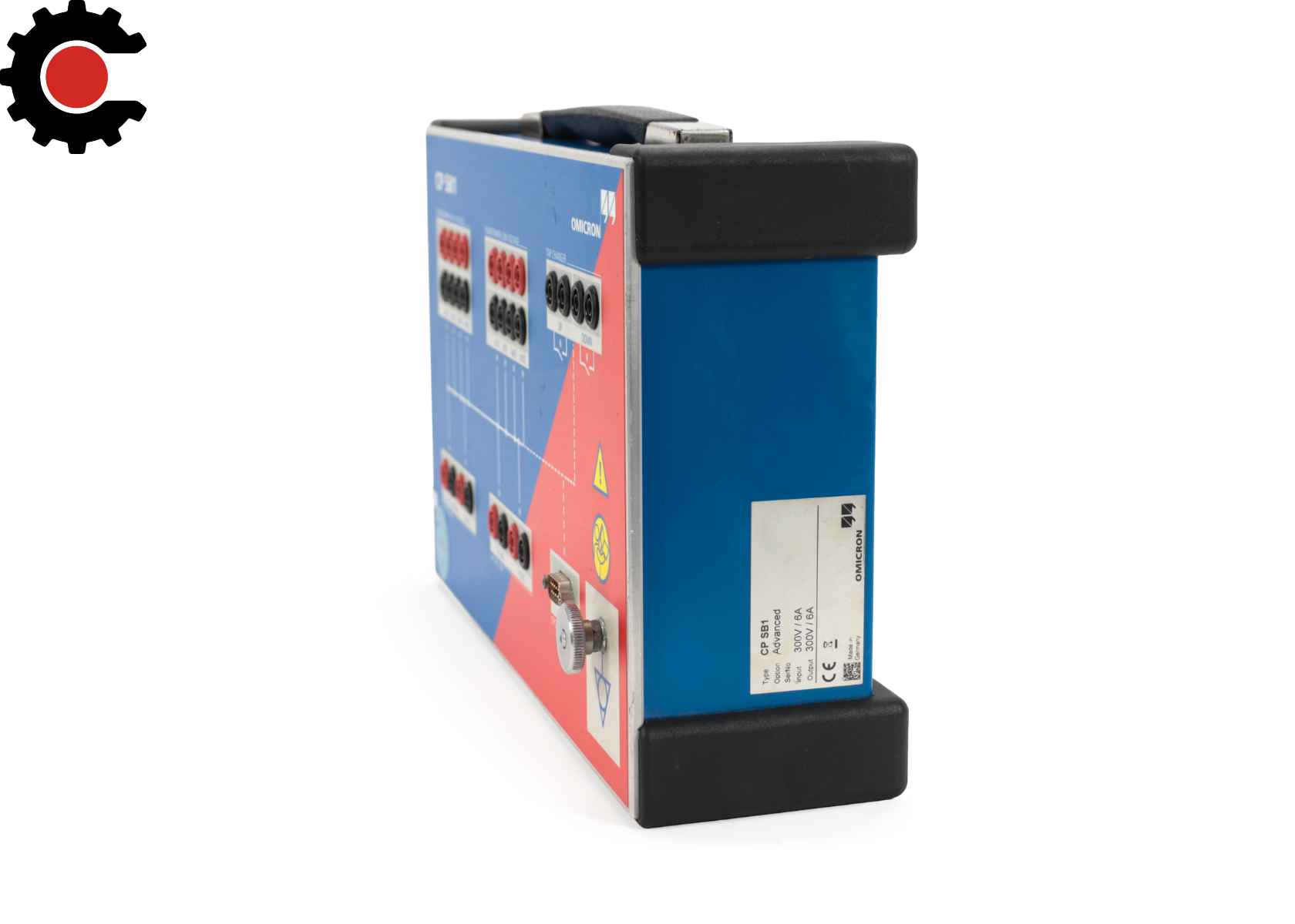
| AC Input / V1 AC Output | 300 Veff maximum |
| DC Input | 6 A DC maximum |
| Transformer High- and Low-Voltage Connections | 300 Veff maximum between all connectors and ground |
| Tap Changer Contact Type | Two potential-free, short-circuit-protected contacts |
| Tap Changer Contact Voltage | 0 to 240 V AC; AC only |
| Tap Changer Overvoltage Category | Category II |
| Contact Resistance | 4 Ω maximum per contact |
| Continuous Contact Current | 0.9 A rms |
| Overvoltage Protection | Surge arrestors on transformer-side connections, AC/DC input, V1 AC output, and V DC output |
| Operating Behavior | |
| Phase Switching | Relay switching matrix controlled through the CPC 100 serial interface |
| Tap Changer Control | Potential-free contacts for tap-up and tap-down operation |
| Manual Operation | Manual wiring mode supported for special measurements and single-phase transformers |
| Discharge Indication | Intermittent acoustic signal during discharge |
| Connection Indication | Double acoustic signal after a correct connection is established |
| Environmental Conditions | |
| Operating Temperature | 14 to 131 °F |
| Storage and Transportation Temperature | -4 to 158 °F |
| Maximum Operating Altitude | 2,000 m |
| Relative Humidity | 5% to 95%, non-condensing |
| Vibration | IEC 60068-2-6; 10 to 150 Hz; 2 g continuous; 20 cycles per axis |
| Shock | IEC 60068-2-27; 15 g for 11 ms, half-sinusoid; 3 shocks per axis |
| Protection Rating | IP20 according to EN 60529 |
| Safety and Compliance | |
| EMC Emissions | EN 61326-1 Class A; IEC 61326-1 Class A; FCC Part 15 Subpart B Class A |
| EMC Immunity | EN 61326-1; IEC 61326-1 |
| Certified Safety Standards | EN 61010-1; IEC 61010-1; UL 61010-1 |
| Applicable High-Voltage Test Practices | IEEE 510; EN 50191; EN 50110-1 |
(Including Calibration Support & Trade-In Options)