
12-40V

Features:
1. New and old version available
2. Made of high quality materials, quality guaranteed
3. Instantaneous braking capability
4. Extremely simple and convenient control, only 3 input lines are needed to control the motor
5. Suitable for all types of microcontroller IO port direct control, but also through the analog input control motor forward and reverse
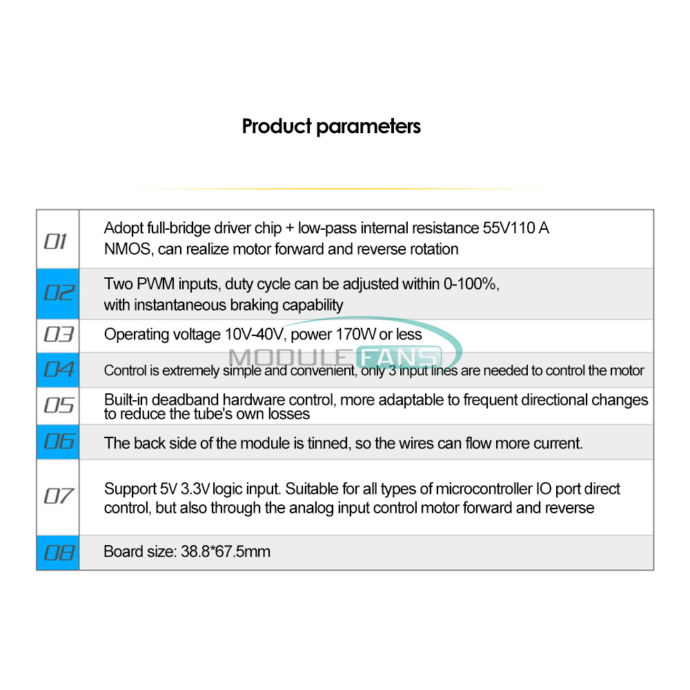
Product parameters.
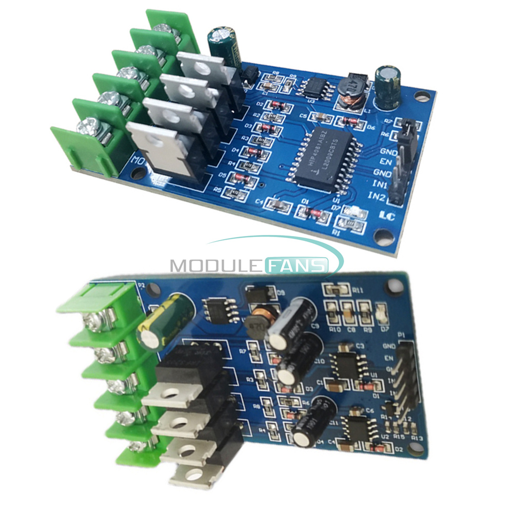
Adopt full-bridge driver chip + low-pass internal resistance 55V110A NMOS, can realize the motor forward and reverse rotation
Two PWM inputs, duty cycle adjustable within 0-100%, with instantaneous braking capability
Operating voltage 12-40V, power below 170W
Extremely simple and easy to control, only 3 input lines are required to control the motor
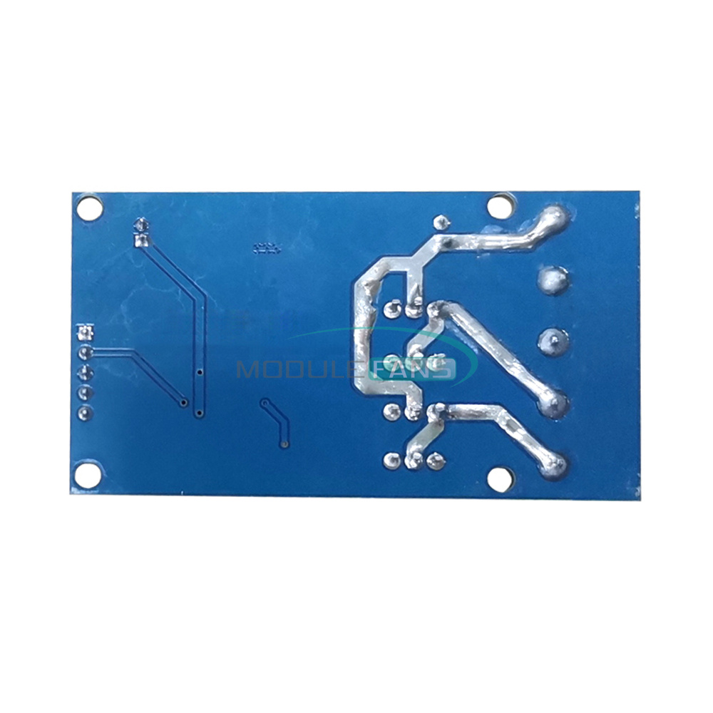
Built-in deadband hardware control, more adaptable to frequent commutation to reduce the loss of the tube itself Tin-plated on the back of the module, the wire can flow through a larger current
Support 5V, 3.3V logic input, suitable for all types of microcontroller IO port direct control, also can control the motor forward and reverse through the analog input
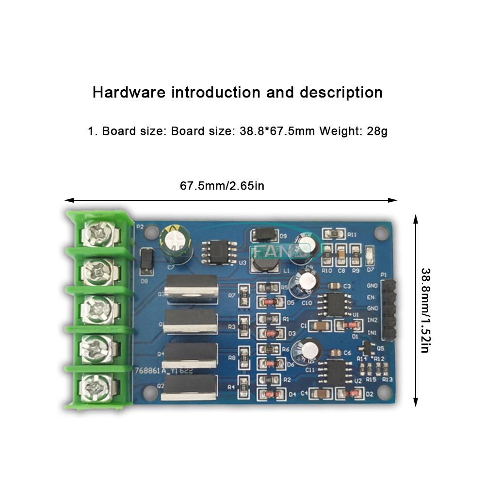
Board size:38.8*67.5mm
Adopt full-bridge driver chip + low-pass internal resistance 55V110A NMOS, can realize the motor forward and reverse rotation
Two PWM inputs, duty cycle adjustable within 0-100%, with instantaneous braking capability
Operating voltage 12-40V, power below 170W
Extremely simple and easy to control, only 3 input lines are required to control the motor
Built-in deadband hardware control, more adaptable to frequent commutation to reduce the loss of the tube itself Tin-plated on the back of the module, the wire can flow through a larger current
Support 5V, 3.3V logic input, suitable for all types of microcontroller IO port direct control, also can control the motor forward and reverse through the analog input
Board size:38.8*67.5mm
Instructions for use:
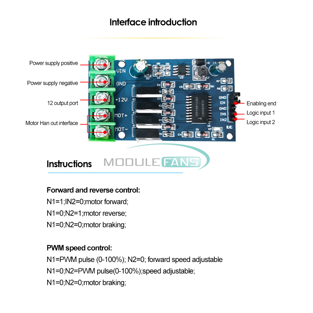
Forward and reverse control:
IN1= 1; IN2= 0; motor forward
IN1= 0; IN2=1;motor reverse
IN1= 0; IN2 = 0; motor braking
PWM speed control:
IN1= PWM pulse (0-100% ); IN2 = 0; adjustable forward speed
IN1= 0; IN2 = PWM pulse (0-100%); Reverse speed adjustable
IN1 = 0; IN2 = 0; motor braking
Forward and reverse control:
IN1= 1; IN2= 0; motor forward
IN1= 0; IN2=1;motor reverse
IN1= 0; IN2 = 0; motor braking
PWM speed control:
IN1= PWM pulse (0-100% ); IN2 = 0; adjustable forward speed
IN1= 0; IN2 = PWM pulse (0-100%); Reverse speed adjustable
IN1 = 0; IN2 = 0; motor braking
Shipping list:
Module X1
Module X1
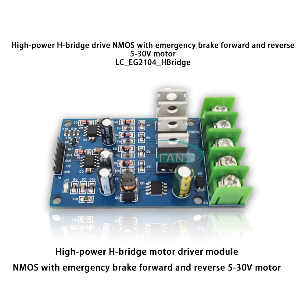
5-30V
Description:
1. Using two-way half-bridge driver chip + low-pass internal resistance 55V110A NMOS, the motor can be forward and reversed.
2. Two-way PWM input duty cycle can be adjusted within 0-99%, with instant braking ability!
3. The working voltage is 5V-30V, and the power is below 170W.
4. The control is extremely simple and convenient, only 3 input lines are needed to control the motor.
5. The chip has built-in dead zone hardware control, which can better adapt to frequent commutation and reduce the loss of the tube itself.
6. Support 5V, 3.3V logic input suitable for direct control of IO ports of various types of microcontrollers.
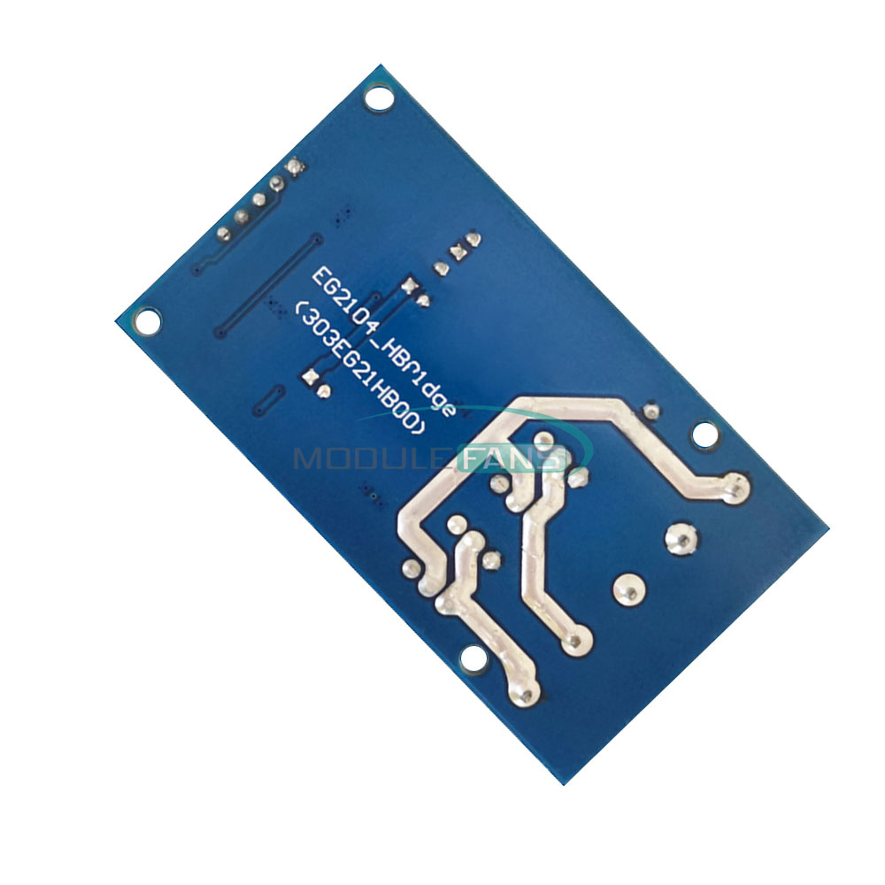
7. The back of the module is tinned, and the wires can flow more current.
1. Using two-way half-bridge driver chip + low-pass internal resistance 55V110A NMOS, the motor can be forward and reversed.
2. Two-way PWM input duty cycle can be adjusted within 0-99%, with instant braking ability!
3. The working voltage is 5V-30V, and the power is below 170W.
4. The control is extremely simple and convenient, only 3 input lines are needed to control the motor.
5. The chip has built-in dead zone hardware control, which can better adapt to frequent commutation and reduce the loss of the tube itself.
6. Support 5V, 3.3V logic input suitable for direct control of IO ports of various types of microcontrollers.
7. The back of the module is tinned, and the wires can flow more current.
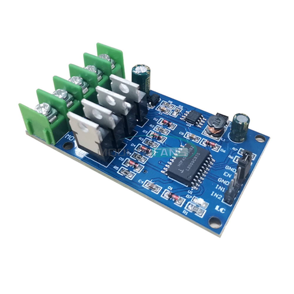
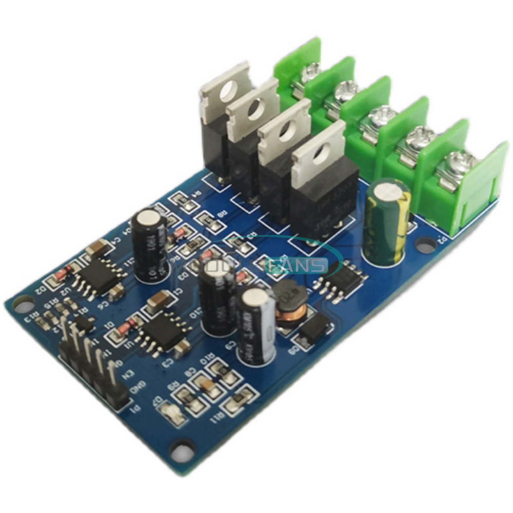
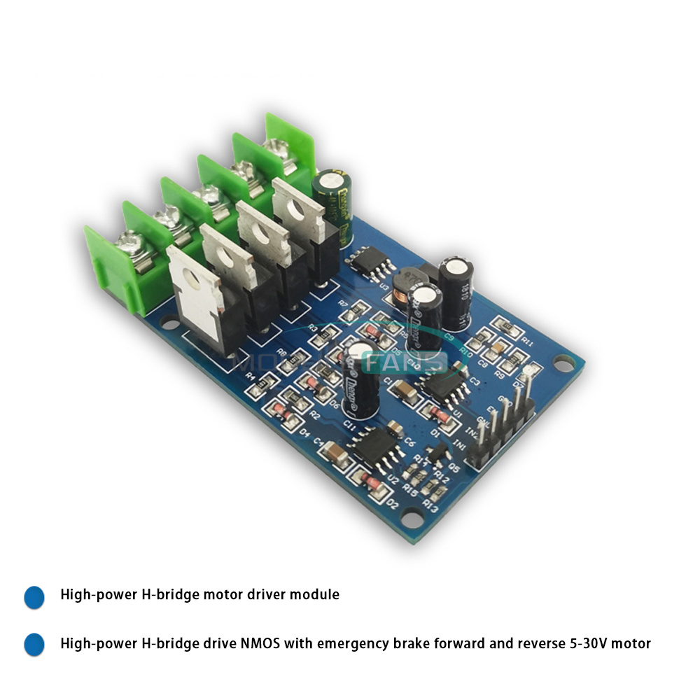
The high-power H-bridge motor driver module is composed of two half-bridge driver ICs and four external NMOS transistors, with low heat generation and good braking effect.
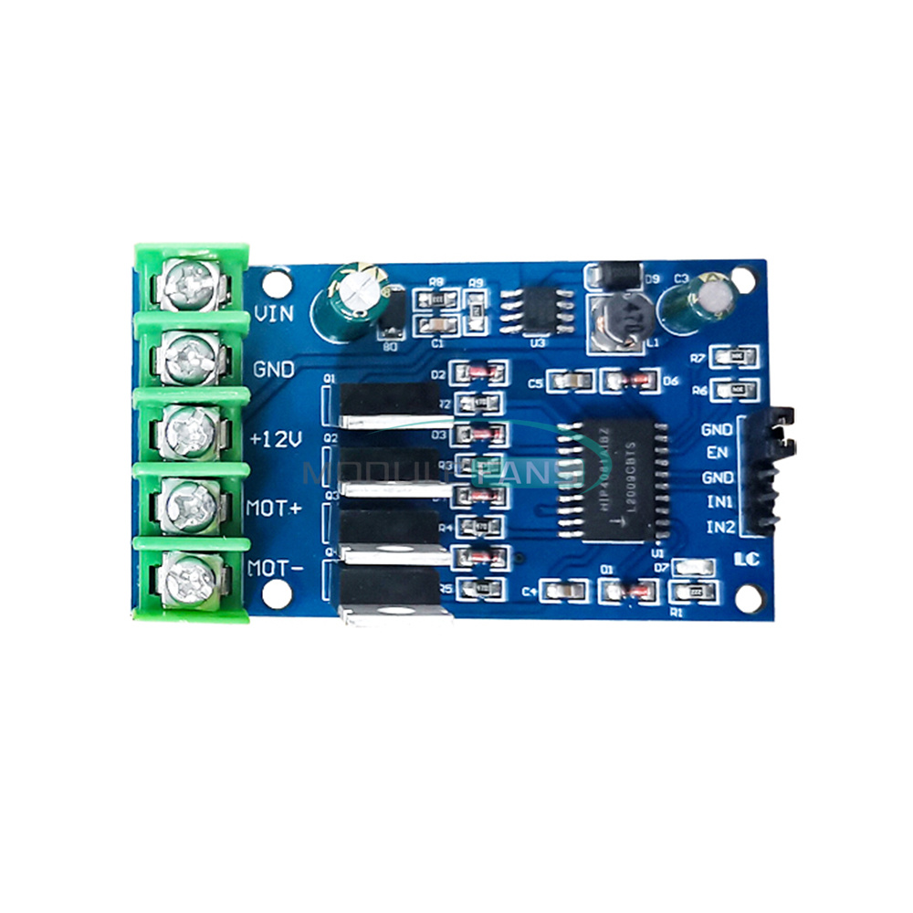
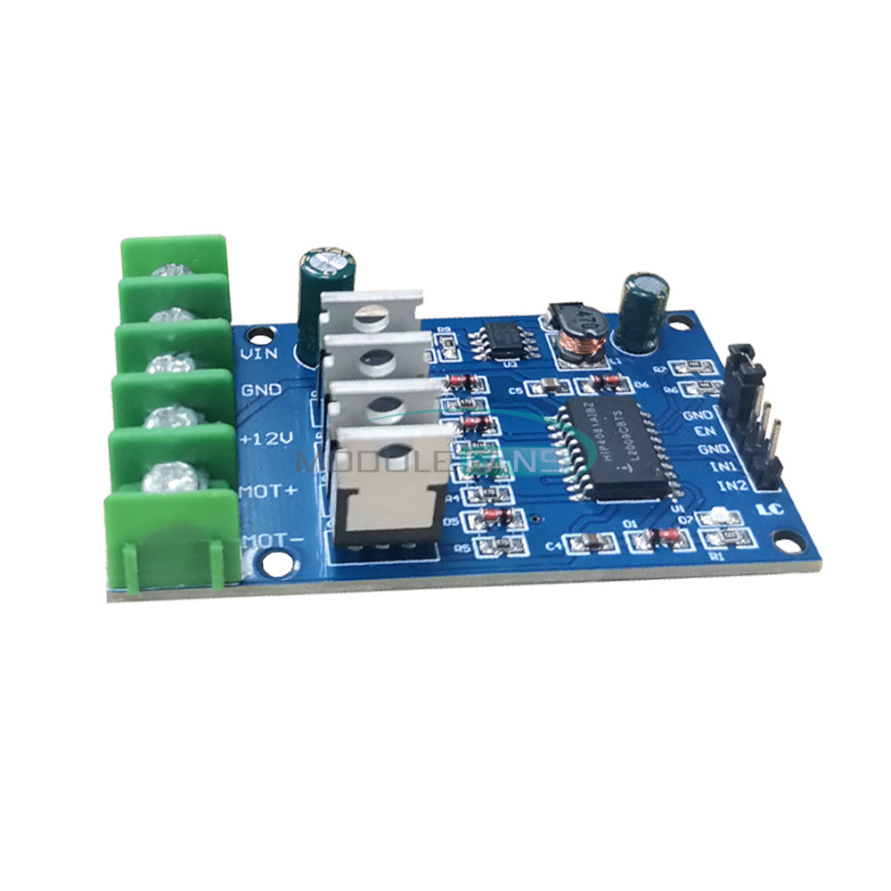
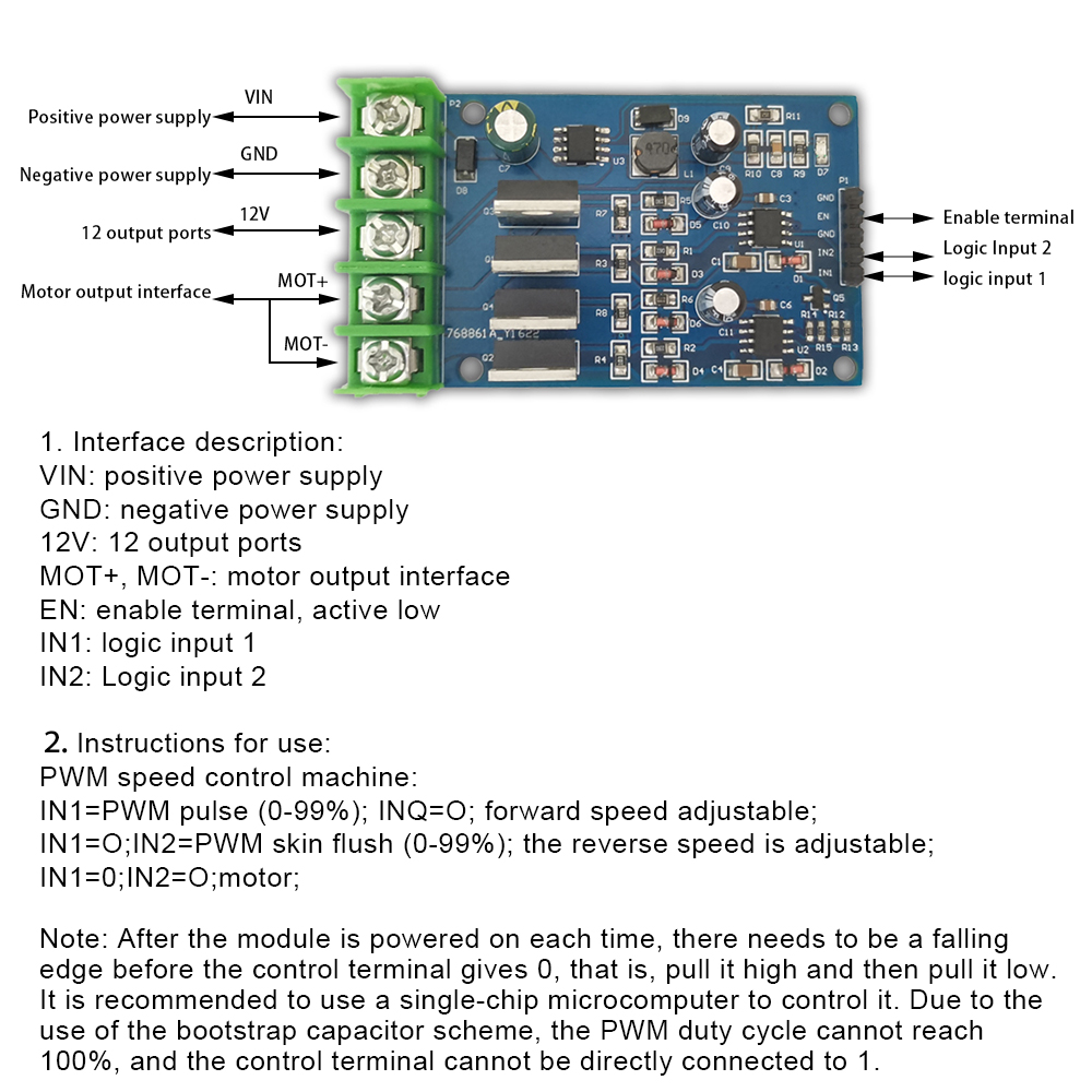
1. Interface description: VIN: positive power supply;
GND: negative pole of power supply;
12V: 12V output port
MOT+, MOT-: motor output interface
EN: enable terminal, active low
IN1: logic input 1
IN2: Logic input 2
2 Instructions for use: PWM speed control air system;
IN1=PWM pulse (0-99%) ;IN2=0;forward speed adjustable;
IN1=0;IN2=PWM pulse (0-99%); reverse speed adjustable;
IN1=0;IN2=0;motor brake;
Note: After the module is powered on each time, there needs to be a falling edge before the control terminal gives 0, that is, pull it high and then pull it low. It is recommended to use a single-chip microcomputer to control it.
Due to the use of the bootstrap capacitor scheme, the PWM duty cycle cannot reach 100%, and the control terminal cannot be directly connected to 1.
Package include:
1*MODULE
1*MODULE
1. We Ship to Worldwide
2. We ship your orders within 1-2 business days after the payment cleared.
3. Item shipped from China via china Post Airmail, reach most of the countries within 2 to 4 weeks.
4. Delivery time depends on destination and other factors, it may takes up to 20 days. If you don't receive
the item after 30 days,please keep in touch with us, we'll investigate and solve the delivery problem.
5. Import duties, taxes, and charges are not included in the item price or shipping cost. These charges
are the buyer's responsibility. Please check with your country's customs office to determine what these
additional costs will be prior to bidding or buying.
ShenZhen
1. We accept PAYPAL only.
2. Payment must be made within 7 days of auction closing (Unpaid dispute will automatically open when item
is not paid in 7 days).
3. PLEASE NOTE: SHIPPING&HANDING DOES NOT INCLUDE DUTIES, LOCATL TAXES OR ANY OTHER IMPORTATION FEES.
4. Please list your special requests (color, packages, value of declaration, etc.) in the EBAY NOTES SECTION
when you make payment
1. Customer satisfaction is our top goal. All products are quality checked. They are new and in good
condition when shipped to our customers. If product is defective or damage upon arrival, or wrong
product shipped, please keep in touch with us immediately. Returns accepted within 14 days of delivery date
and item must be in original new condition, not worn or altered in any way with attached tags & wrap.
Otherwise deal is final. Return shipping must be paid by buyer.
2. Please keep in touch with us first if you have anyproblems/questions/concerns. We will be happy to resolve
any issues you may have in a cordial and friendly manner.
3. We appreciate your Positive Feedback, and will do the same in return. PLEASE DO NOT leave
negative feedback without first communication with us. Please allow max 24 HOURS for us to respond
We maintain high standards of excellence and strive for 100% customer satisfaction! Feedback is
very important to us. We request that you keep in touch with us immediately BEFORE you give us neutral or
negative feedback, so that we can satisfactorily address your concerns.It is impossible to address
issues if we do not know about them!
