
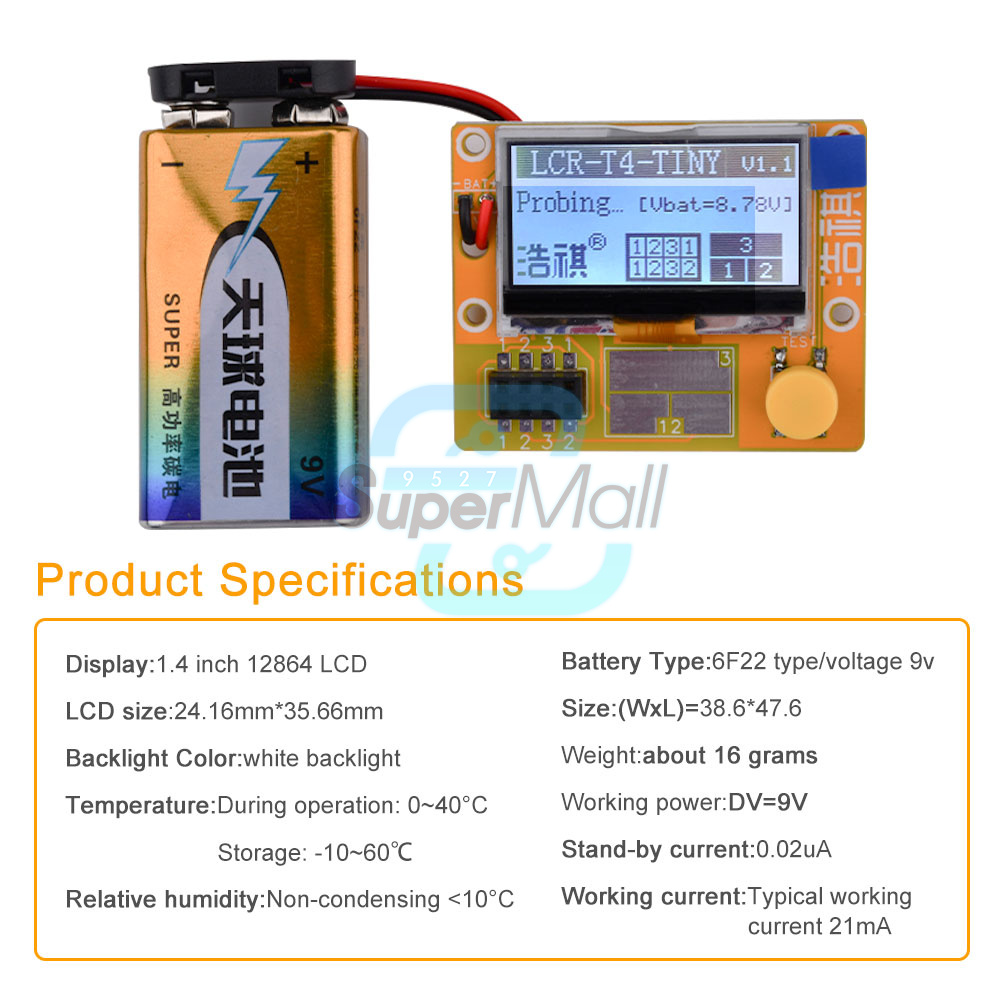

Description:
Using 12864LCD graphic display, intuitive information, large information content
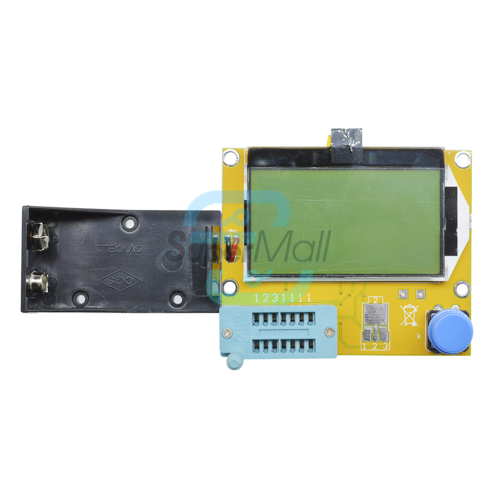
Powered by 6F22 9v battery, easy to get cheaper
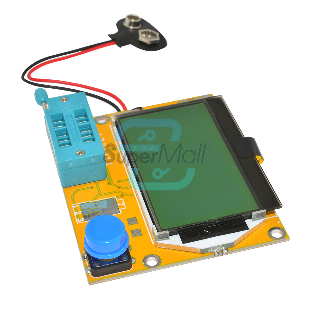
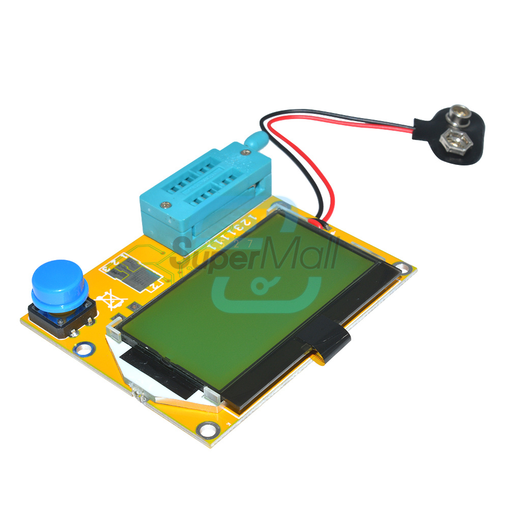
2*4 test seat and SMD component test area, in-line and SMD component testing is convenient and fast
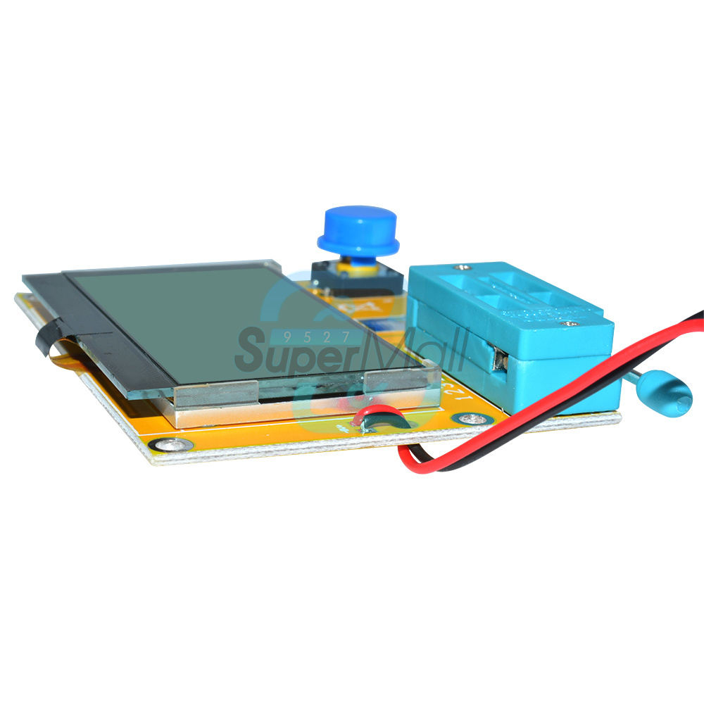
Ultra-small LCD, delicate display
Automatic identification of pin sequence, fool test
High-precision key components are used to ensure test accuracy
Ultra-low power consumption, the power consumption is only 21ma, the standby current is only 20na, and the standby time is very long.
One-touch operation, fast and labor-saving
Ultra-small size, easy to use
LCD size: 24.16mm*35.66mm
Backlight Color: White Backlight
Temperature: Operation: 0~40℃ Storage: -10~60℃
Relative humidity: non-condensing <10°C
Battery type: 6F22 / voltage 9v
Working power supply: DV=9V
Standby current: 0.02uA
Working current: typical working current 21mA
2. The standby current is as small as 20na, and the standby power is negligible for long standby time, and the battery can be used for power supply.
3. Automatically detect PNP and NPN type bipolar transistors, N, P channel MOSFET, JFET, diode, double diode, thyristor thyristor (thyristor), triode, resistor, capacitor, capacitor ESR value.
4. Automatically detect the pin layout and give the label according to the actual sequence.
5. Measure the current amplification factor β of the bipolar transistor, the threshold voltage of the emitter junction, and the ICE leakage current.
6. Darlington transistors can be identified by high threshold voltage and high current amplification factor.
7. For bipolar transistors, MOSFET protection diode detection and forward voltage drop Uf.
8. Measure the threshold voltage Vt and gate capacitance C of the MOSFET.
9. Detect and determine the forward voltage of the emitter transistor and the magnification and base of the transistor and MOSFET protection diode.
10. Support simultaneous measurement and symbol display of two resistances. Both ends of the displayed resistance symbol are the connected tester probe numbers (1-3), and the adjustable potentiometer can also be measured
11. The resolution of resistance measurement is 0.1 ohm, and the highest measurement value is 50M ohm.
12. The highest four digits of the capacitance are displayed, and the capacitance value ranges from 25pf (8MHz clock, 50pF@1MHz clock) to 100mF. Resolution up to 1pF (@8MHz clock).
13. The equivalent series resistance (ESR) capacitance value of capacitors above 2UF can be measured with a resolution of 0.01 ohms and a two-digit value displayed.
14. It is possible to display the symbol of the correct direction for both diodes and to display the forward voltage drop.
15. The LED is detected as a diode, it will flash several times continuously during the test, and the double light-emitting diode is detected as a double diode.
16. Zener diodes can be tested, if the reverse breakdown voltage is lower than 4.5V it will show as two diodes.
17. The capacitance value of the reverse of a single diode can be measured. Bipolar transistors can also be measured. At this time, the base and collector or emitter must be connected.
18. Only one measurement is needed to find out the connection of the full bridge.
19. The maximum capacitance test is 1000000uf, and the best test range is 0.2nF~7000uF.
20. The inductance test range is: 0.01mH~20H, more than 20H, resistance below 2100 ohms will be recognized as inductance, the measurement result only shows a single inductance, and the inductance value is displayed.
21. The test time is about two seconds, and the measurement time of bulk capacitance and inductance will be extended with the actual value.
22. Automatically shut down, after the test, the test result will always be displayed for about 25 seconds, and then shut down.
23. Be sure to discharge the capacitor before testing the capacitor, otherwise the tester will be burned.
24. Types of power devices and amplifiers, transformers, etc. are not allowed to be tested or cannot be tested.
Tear off the screen protector before use for a better display!
Discharge before use! Be sure to discharge the capacitor before the capacitor test, otherwise there will be a danger of burning the machine, and the damage will be at your own risk!
Contrast adjustment method:
After the test result is displayed on the screen, double-click the button to adjust the number displayed in the center of the screen. At this time, single-press the button, the corresponding value will increase, and double-click to save when satisfied. (The reference value is 23-28 is the best)
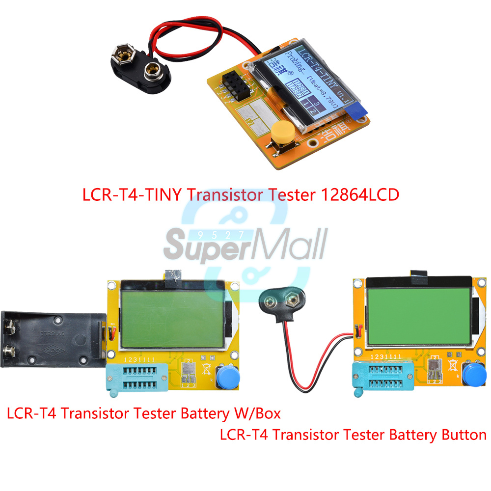
Transistor Tester X1
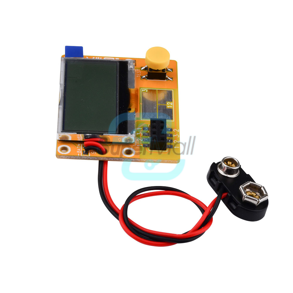
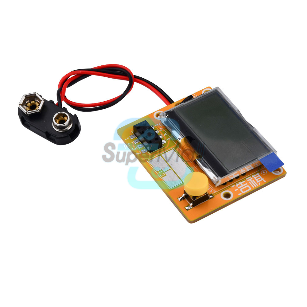
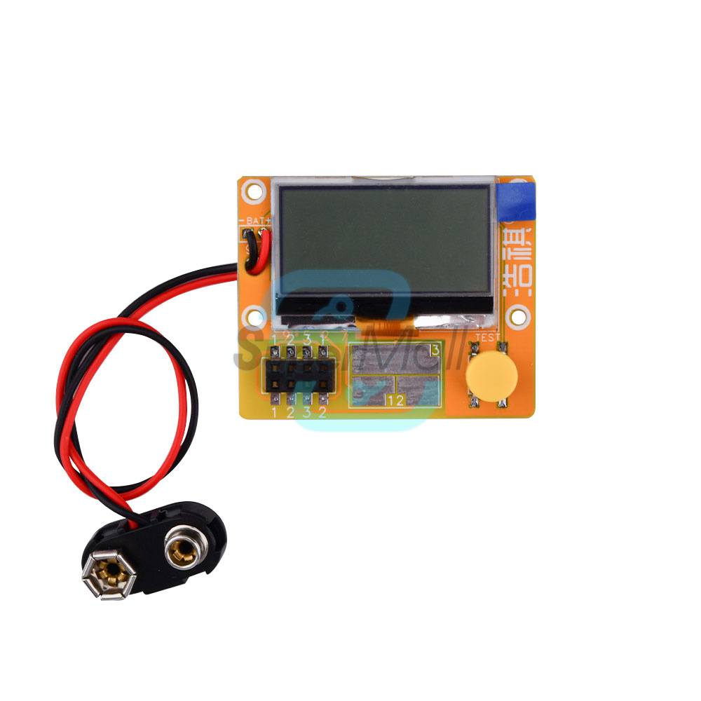
LCR-T4 Transistor Tester Battery Button
Features :
1,2013 latest M328 version of the software ,more functions.Chip: MTY328P
2.128*64 big Backlight LCD display,only 2mA when stand by.
3,Using 9V battery (Not included)
Test ranges:
Inductors, capacitors , diodes, dual diode , mos, transistor, SCR , the regulator, LED tube , ESR,
Resistance,Adjustable potentiometer
Resistance :0.1 ohm resolution, maximum 50M ohm
Capacitor :25pf -100,000 uf
Inductors : 0.01mh-20H
Function:
1:Automatic detection of NPN and PNP transistors, n-channel and p-channel MOSFET,
diode (including double diode), thyristor, transistor, resistor and capacitor and other components
2: Automatic test the pin of a component, and display on the LCD
3:Can detect the transistor, MOSFET protection diode amplification coefficient
and the base to determine the emitter transistor forward biased voltage
4: Measure the gate and gate capacitance of the MOSFET threshold voltage
5:Use 12864 liquid crystal display with green backlight
Specifications: For you reference
1,One -button operation, automatic shutdown .
2,Only 20nA shutdown current.
3,Automatically detect NPN, PNP bipolar transistors , N -channel and P -channel MOS FET,
JFET , diodes , two diodes, thyristors small power unidirectional and bidirectional thyristor.
4,Automatic identification components pin arrangement .
5,Measuring bipolar transistor current amplification factor and base - emitter threshold voltage.
6,Via the base - emitter threshold voltage and high current amplification factor to identify Darlington transistors.
7,Can detect bipolar transistors and MOS transistors protection diodes.
8,Measuring the gate MOS FET threshold voltage and the gate capacitance.
9,Can simultaneously measure two resistors and resistor symbol is displayed.
Displayed on the right with a decimal value of 4 .
Resistance symbol on both sides shows the pin number.
So you can measure the potentiometer.
If the potentiometer wiper is not transferred to an extreme position ,
we can distinguish the middle and both ends of the pin.
10,Resistance measurement resolution is 0.1 ohms , 50M ohms can be measured .
11,Can measure capacitanceCan measure capacitance of 30pF-100mF , resolution 1pF.
12.2uF more capacitors can simultaneously measure the equivalent series resistance ESR values.
The two can be displayed with a decimal value , resolution 0.01 ohms.
13,Can be in the correct order and the diode symbol display two diodes , and gives the diode forward voltage.
14.LED is detected as a diode forward voltage higher . Combo of the LED is identified as two diodes.
15,Eeverse breakdown voltage is less than 4.5V Zener diode can be identified.
16,Can measure a single diode reverse capacitance.
If the bipolar transistor connected to the base and collector or emitter of a pin ,
it can measure the collector or emitter junction reverse capacitance .
18 can be obtained with a single measurement rectifier bridge connection.
Notice: Before measuring capacitance , the capacitor must be discharged , otherwise very likely damage the meter .
Package Included:
1PCS * Mega328 Transistor Tester Diode Triode Capacitance ESR Meter MOS PNP/NPN M328
LCR-T4 Transistor Tester Battery W/Box
Features :
1,M328 version of the software ,more functions.Chip: Atmega328
2.128*64 big Backlight LCD display,only 2mA when stand by.
3.Using 9V battery (Not included)
Test ranges:
Inductors, capacitors , diodes, dual diode , mos, transistor, SCR , the regulator, LED tube , ESR,
Resistance,Adjustable potentiometer
Resistance :0.1 ohm resolution, maximum 50M ohm
Capacitor :25pf -100,000 uf
Inductors : 0.01mh-20H
Function:
1:Automatic detection of NPN and PNP transistors, n-channel and p-channel MOSFET,
diode (including double diode), thyristor, transistor, resistor and capacitor and other components
2: Automatic test the pin of a component, and display on the LCD
3:Can detect the transistor, MOSFET protection diode amplification coefficient
and the base to determine the emitter transistor forward biased voltage
4: Measure the gate and gate capacitance of the MOSFET threshold voltage
5:Use 12864 liquid crystal display with green backlight
2.Only 20nA shutdown current.
3.Automatically detect NPN, PNP bipolar transistors , N -channel and P -channel MOS FET,
JFET , diodes , two diodes, thyristors small power unidirectional and bidirectional thyristor.
4.Automatic identification components pin arrangement .
5.Measuring bipolar transistor current amplification factor and base - emitter threshold voltage.
6.Via the base - emitter threshold voltage and high current amplification factor to identify Darlington transistors.
7.Can detect bipolar transistors and MOS transistors protection diodes.
8.Measuring the gate MOS FET threshold voltage and the gate capacitance.
9.Can simultaneously measure two resistors and resistor symbol is displayed.
Displayed on the right with a decimal value of 4 ,Resistance symbol on both sides shows the pin number. So you can measure the potentiometer. If the potentiometer wiper is not transferred to an extreme position, we can distinguish the middle and both ends of the pin.
10.Resistance measurement resolution is 0.1 ohms , 50M ohms can be measured .
11.Can measure capacitanceCan measure capacitance of 30pF-100mF , resolution 1pF.
12.2uF more capacitors can simultaneously measure the equivalent series resistance ESR values.
The two can be displayed with a decimal value , resolution 0.01 ohms.
13.Can be in the correct order and the diode symbol display two diodes , and gives the diode forward voltage.
14.LED is detected as a diode forward voltage higher . Combo of the LED is identified as two diodes.
15.Eeverse breakdown voltage is less than 4.5V Zener diode can be identified.
16.Can measure a single diode reverse capacitance.
If the bipolar transistor connected to the base and collector or emitter of a pin ,
17.It can measure the collector or emitter junction reverse capacitance .
18. can be obtained with a single measurement rectifier bridge connection.
Notice: Before measuring capacitance , the capacitor must be discharged , otherwise very likely damage the meter .
Package Include:
1 x Mega328 Transistor Tester Diode Triode Capacitance ESR Meter MOS PNP/NPN M328
1.We accept PayPal payment ONLY, and must be received within 5 days from the date of purchase.
2. It is easy and safe for you to pay by credit cards, debit cards, bank transfers and PayPal account balances.
3.Buyers are responsible for import duties,custom fees and taxes, if any, please check your country.
1.We only ship to the confirmed address provided by eBay. please make sure your ebay address is 100% matches the address you would like us to ship to. If not, please let us know before we sent you the package, or we will not be responsible for any loss. hope you could understand.
2.Orders will be processed instantly and dispatched within 1-2 business days except hoilday, so we do NOT accept any email/message note after you place orders.
3.All package need to wait 30 days,Please take care it.Less than 30 days,we can't take a refund.
2. If you do not satisfy with our items. Please simply return to us within 30 Days in original condition. Just pay for the returned postage. Then we can issue full refund or resend the item to you after the returned item arrived at our warehouse.
3. Please include your eBay ID and item number with any email requests.
2.Please DON'T leave negative or neutral feedback if you haven't received item in 30 days, because we have mentioned the shipping time repeatedly.
2.Just contact us using the " Ask the seller a question" link on eBay.
3.Our aim is to provide Top Level Customer Service, normally so we will try our best to solve any problem.
Am 12.01.2023 hat der Verkäufer die folgenden Angaben hinzugefügt: