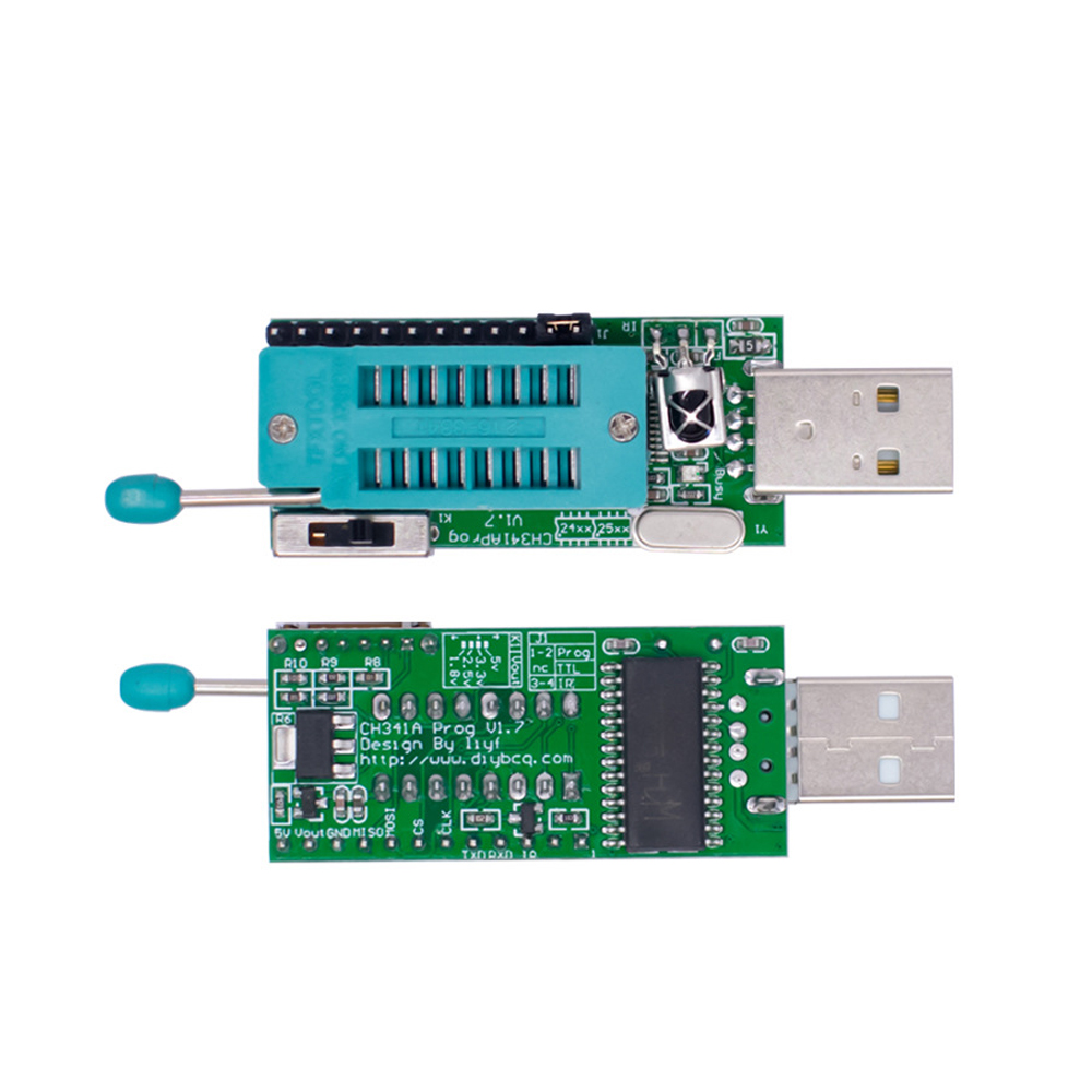
CH341A Programmer V1.7 1.8V Level Conversion W25Q64FW W25Q128FW GD25LQ64
Description:
Item model number: Pro-341A-001
Product Dimensions: 2.54 x 0.87 x 0.59 inches
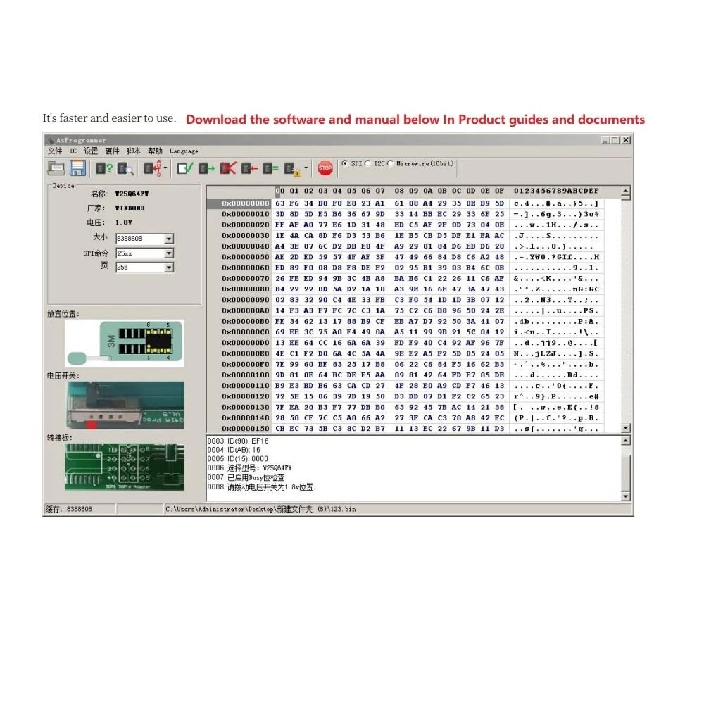
Product instructions and Soft Drivers,Please See follow
Product guides and document: User Manual (PDF)*Integrated dedicated level conversion chip, directly read and write 5v, 3.3v, 2.5v, 1.8v chips
*Integrated infrared code measurement module*
Support programming 24, 25/26, 93, 45, 95 types of chips, our also supports kb9010 kb9012 kb9016 kb9018 kb9022 ec data read and write
*The software is open source, you can add the chip type by yourself, or the source code of the software, not to be stuck by others
*TTL can support to 1.8v level, suitable for special occasions
*Read and write status lights, TTL status lights
*Support TTL self-check
*In the locking seat part, 24xx add a strong pull-down resistor, 25xx add a pull-up resistor
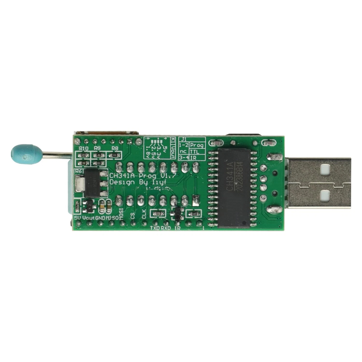
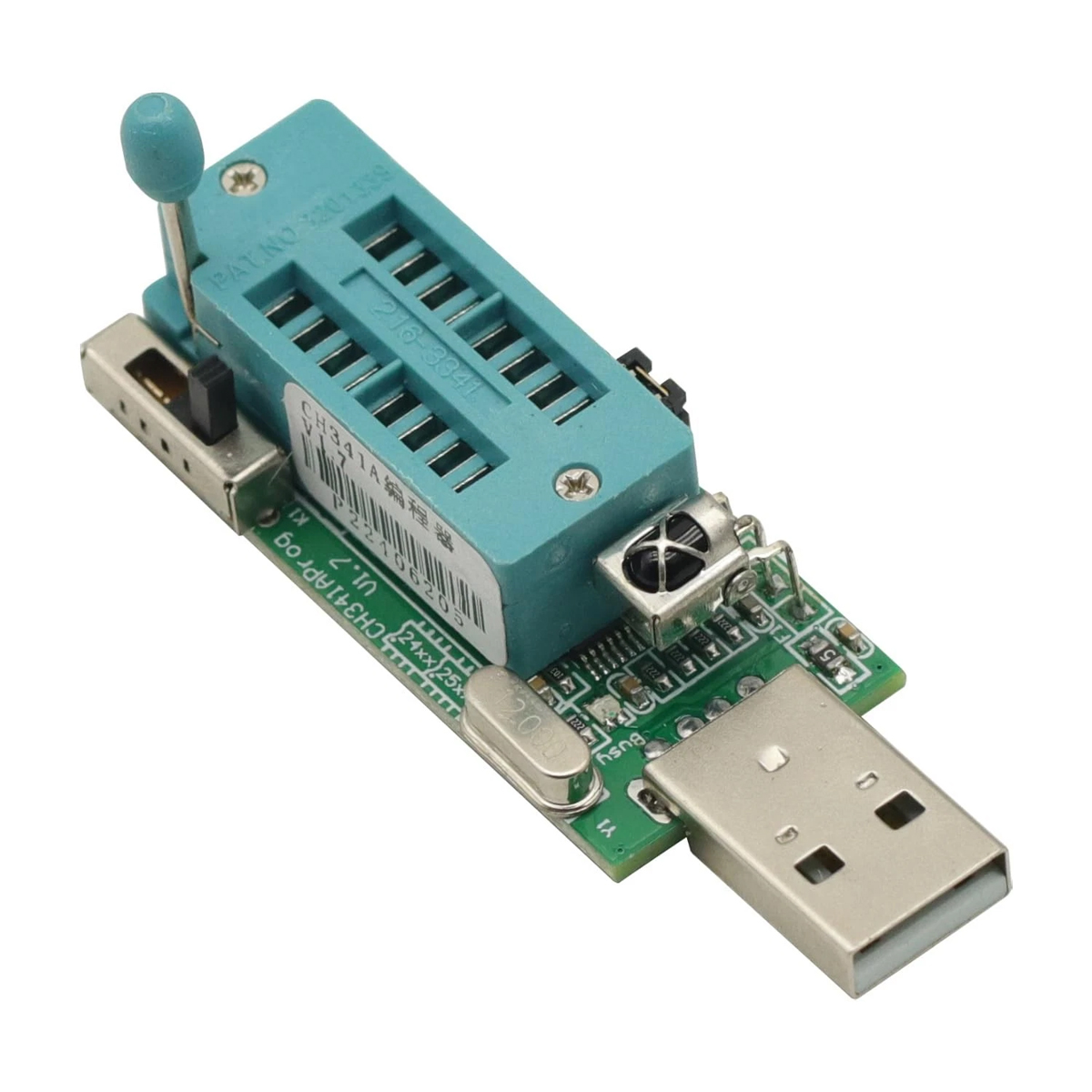
Product descriptionCH341A programmer V1.7 version
*Integrated dedicated level conversion chip, directly read and write 5v, 3.3v, 2.5v, 1.8v chips
*Integrated infrared code measurement module
*Support programming 24, 25/26, 93, 45, 95 types of chips, our also supports kb9010 kb9012 kb9016 kb9018 kb9022 ec data read and write
*The software is open source, you can add the chip type by yourself, or the source code of the software, not to be stuck by others
*TTL can support to 1.8v level, suitable for special occasions
*Read and write status lights, TTL status lights
*Support TTL self-check
*Support to open A SUS cap files directly
*In the locking seat part, 24xx add a strong pull-down resistor, 25xx add a pull-up resistor
Several possibilities and solutions for ch341a programmer clip board (on clip or on board fly-by-wire) failure
25xx series
Sell this programmer quite a long time, encountered a lot of people asked to read and write problems on the board, generally targeted answers, but asked more people, it is necessary to open a special post to explain, lest answer up too much effort!
Quickly determine whether to support the board clip burner.
Clip the chip connected to the programmer, the software point to identify the button, identify the chip probability of burning no problem (individual will not read and write normal, according to the following list of problems troubleshooting)
Generally the following situations:
1, read out the empty or garbled
This generally use our software, point? button to identify the id, mostly FFFFFFF. for this, the subsequent operation can be said to be basically invalid, read out the data are meaningless.
The simplest solution: remove the chip to read and write!
Want to look deeper: check the power supply voltage, communication feet whether the level can not be changed or disconnect the relevant pin circuit, refer to the cause of the problem analysis
2, recognize the id, but read and write is not normal
Read out may be every time there is a discrepancy or not the same, or read out normal, but write always checksum but. This operation may not make much sense.
The simplest solution: remove the chip to read and write!
Want to look deeper: check the power supply voltage, communication foot level can not be changed or disconnect the relevant pin circuit, wp foot is pulled down, refer to the cause of the problem analysis
3, the same board, sometimes can read and write, sometimes not
General write checksum the problem is not big. But in this case, the board read and write instability, communication feet are external circuit interference.
The simplest solution: remove the chip to read and write!
Want to look deeper: check the supply voltage, communication foot level can not be changed or disconnect the relevant pin circuit, refer to the cause of the problem analysis
4, some boards can be clamped directly on the read-write, some can not be
This is mainly a different board circuit design, resulting in different interference. For most of the board to stay on the board with a brush interface, most of the board to consider the issue of brush interference, this type of board is generally directly on the clip is not a big problem.
The simplest way to solve the problem: remove the chip to read and write
Want to look deeper: check the supply voltage, communication foot level can not be changed or disconnect the relevant pin circuit, refer to the cause of the problem analysis
For the above questions, in fact, summarize the board design of the circuit interference caused by (people originally did not burn the chip on the board to consider).
If you consider the direct use of probes or clips or rows of pins in the interface of the burning words, generally in the chip's power supply string a diode, communication io string into the resistor!
Programmers are not designed to be able to read and write online, the use of clips directly on the board chip this type of operation, that is, we take the trick.
In fact, to put it bluntly, as long as you disconnect the chip's 8 wires and other circuits, how to clip or fly the line will not have a problem, the programmer in the board read and write 100% will not have a problem, as long as your connection line is not too long.
Since there is such a need, we still need to explore the feasibility of this operation.
Analysis of the cause of the problem
So what exactly causes the operation of the problem? In general, the following two main reasons:
1, not enough power supply
For the power supply problem, this is easy to understand, sometimes in the board operation to increase the voltage can be read or read and write are normal, this type of board is relatively easy to operate, but must pay attention to do not burn the front-end power supply chip, the loss is not worth the gain. Some boards will be in the power supply pins into the resistor, then you can first weld the resistor in the operation.
Use a multimeter to measure the chip on the clip after the power supply voltage is too large a deviation, generally not more than 5%, such as 3.3v, if the measurement of the voltage is only 3v may not be normal!
Of course, you can increase the power supply voltage by toggling the voltage switch, but this may lead to damage to the chip on the board, their own consideration!
There is also a kind of, clip a clip on the board, the programmer are not recognized, this may be protected, check to see if the clip is reversed or connected to the wrong wire, or the board has a short circuit. Our programmer is designed with short circuit protection, there will be no problem for a short period of time, remove the clip, re-plug the programmer can be.
2、Communication line is occupied
Communication lines are mainly 1 cs, 2 do, 5 di, 6 clk.
This is more complicated, most of the communication line and the main control of the motherboard directly connected to the power on these feet are occupied, the main control to try to read and write the chip, resulting in the programmer can not be sent to the chip, causing the programmer can not be recognized, you can try to disconnect the main control of the motherboard and the chip connection.
There is also a kind of board startup, cpu operation on the chip, then you can find the cpu reset circuit, so that it is in a reset state. Of course there is no that other communication lines are occupied.
Some good board design, will be in a few communication lines into the series of resistors, then it is best to first weld open on the clip read and write. Of course, you can directly clip on the read-write try to do the rest.
Of course, the above two situations have also appeared, corresponding to troubleshooting can be, of course, it is best to remove the chip is convenient.
Our programmer design is designed according to the 500ma current design, voltage regulator is used sot223 package, if the power supply current is not enough, it means that your usb port power supply to 500ma, please replace the usb port integrated into the motherboard or external power supply to try.
The following is a direct motherboard integrated usb port external extension cable, programmer voltage setting 3.3v, vout output serial connection multimeter, led light board test, more than 500ma.
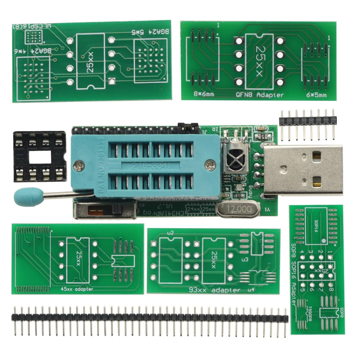
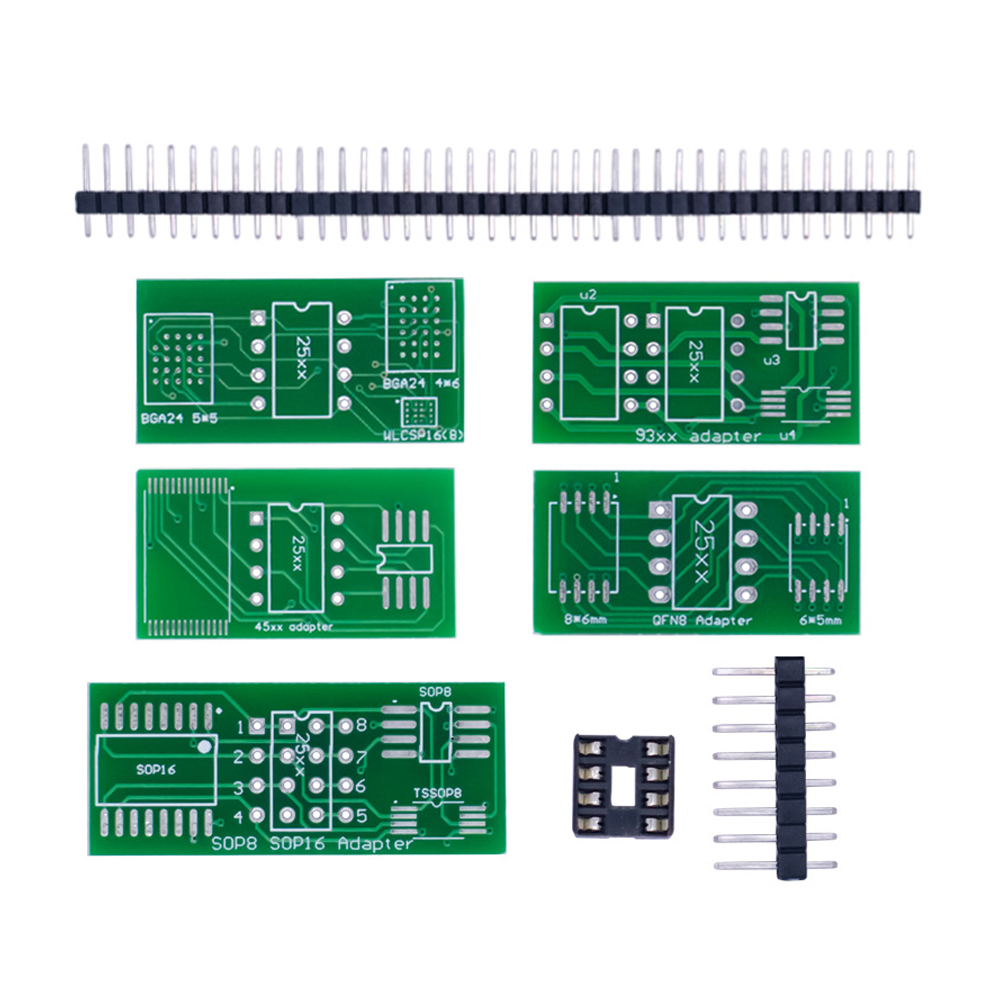
Package included:1Set

On Mar 24, 2026 at 03:59:01 PDT, seller added the following information: