
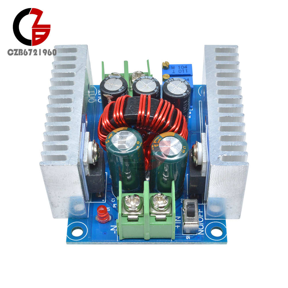
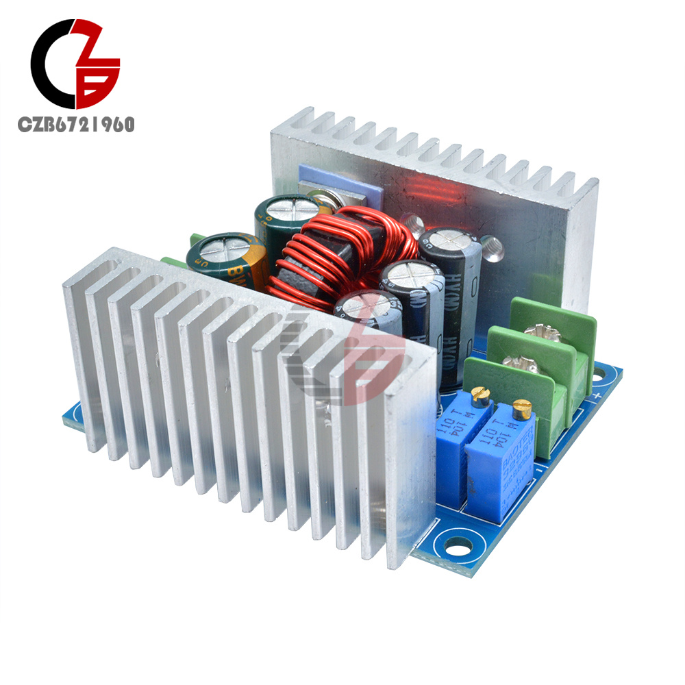
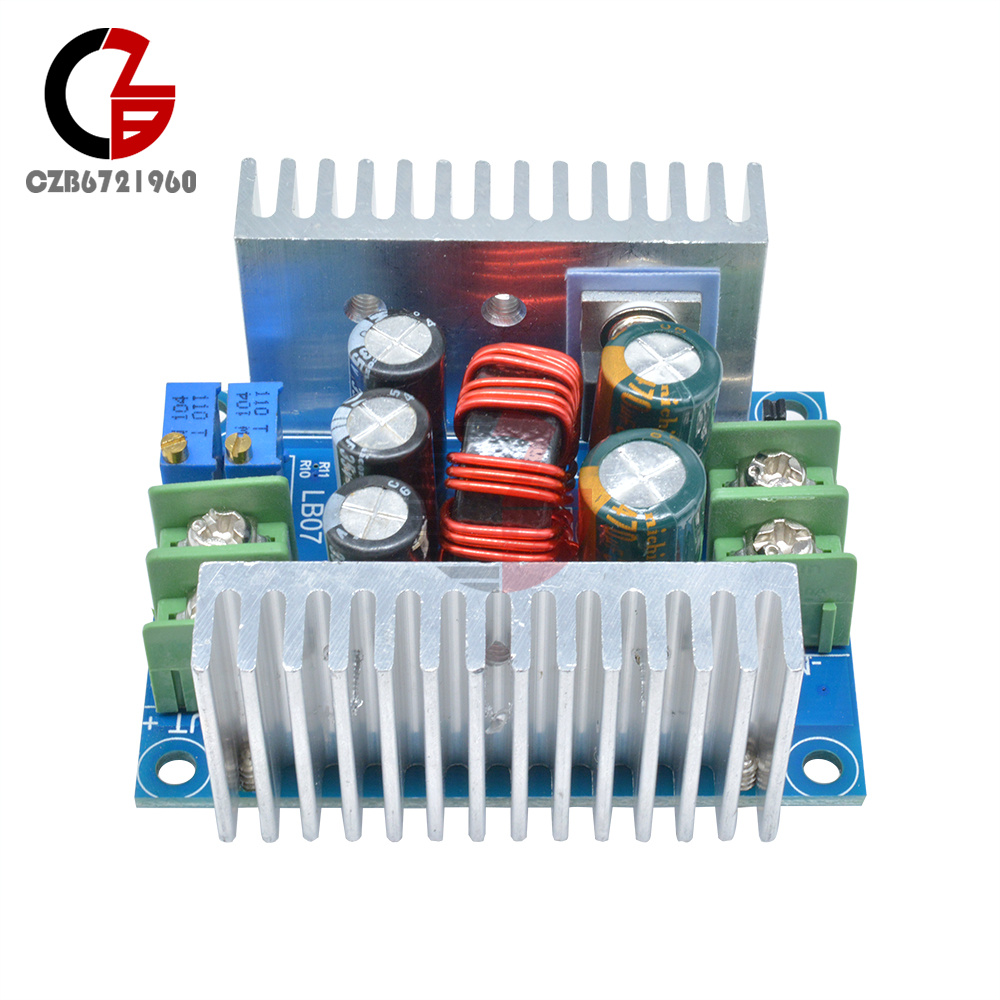
1-10PCS DC 300W Constant Current Adjustable Step-Down Converter Voltage Buck
Popular
Product Introduction
Introduction to Synchronous Rectification Technology:
Synchronous rectification is a new technology that uses specialized power MOSFETs with extremely low on-resistance to replace rectifier diodes, thereby reducing rectification losses. It can significantly improve the efficiency of DC/DC converters and eliminates the dead-zone voltage caused by the Schottky barrier voltage. Power MOSFETs are voltage-controlled devices, and their current-voltage characteristics are linear when turned on. When using a power MOSFET as a rectifier, the gate voltage must remain in phase with the rectified voltage to perform the rectification function; hence, it is called synchronous rectification. Synchronous rectification technology significantly reduces rectification losses at the output of switching power supplies, thereby improving conversion efficiency and reducing heat generation within the power supply itself.
Synchronous rectification is a new technology that uses specialized power MOSFETs with extremely low on-resistance to replace rectifier diodes, thereby reducing rectification losses. It can significantly improve the efficiency of DC/DC converters and eliminates the dead-zone voltage caused by the Schottky barrier voltage. Power MOSFETs are voltage-controlled devices, and their current-voltage characteristics are linear when turned on. When using a power MOSFET as a rectifier, the gate voltage must remain in phase with the rectified voltage to perform the rectification function; hence, it is called synchronous rectification. Synchronous rectification technology significantly reduces rectification losses at the output of switching power supplies, thereby improving conversion efficiency and reducing heat generation within the power supply itself.
Module Parameters:
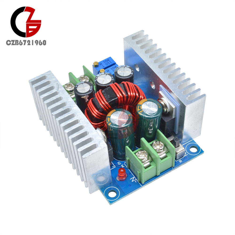
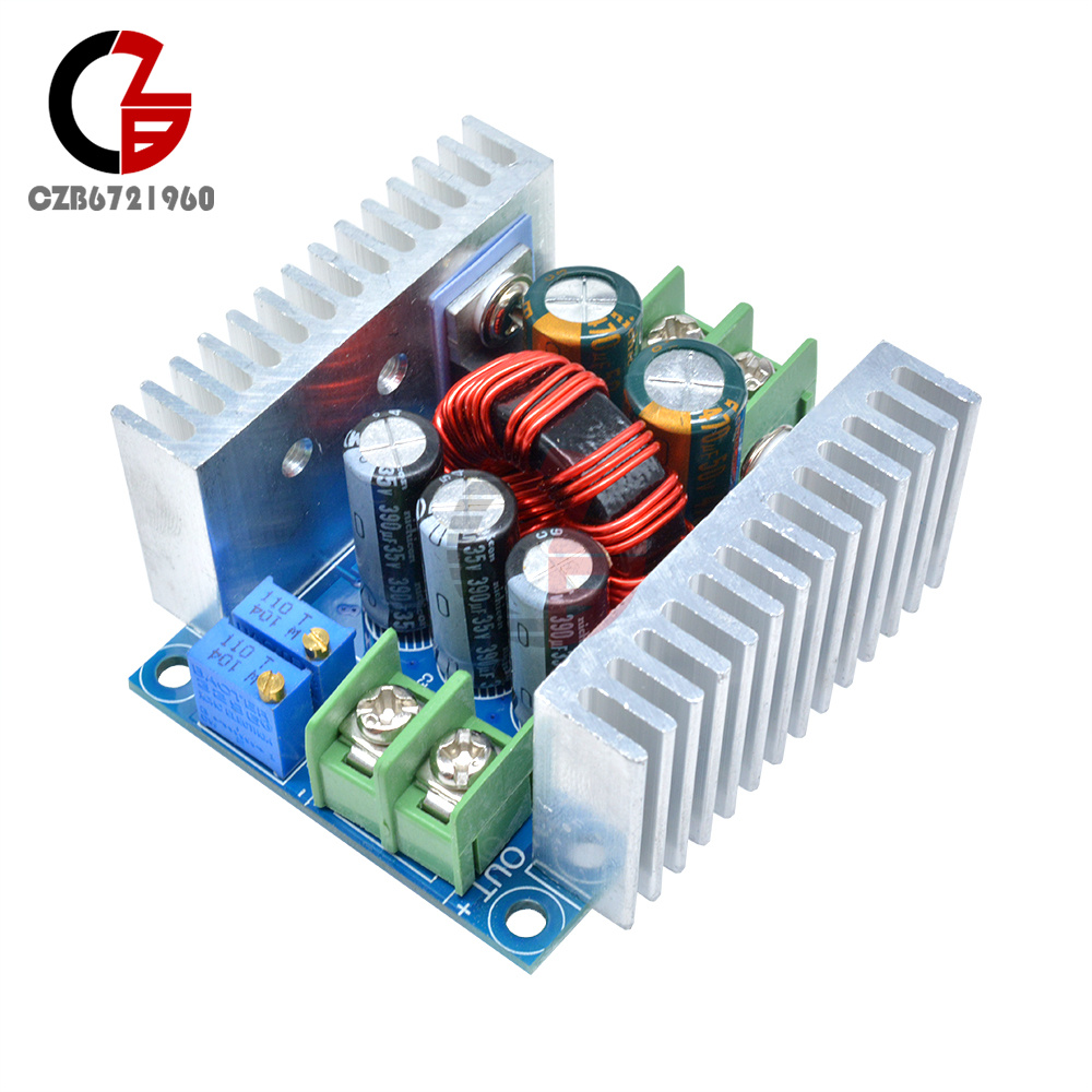
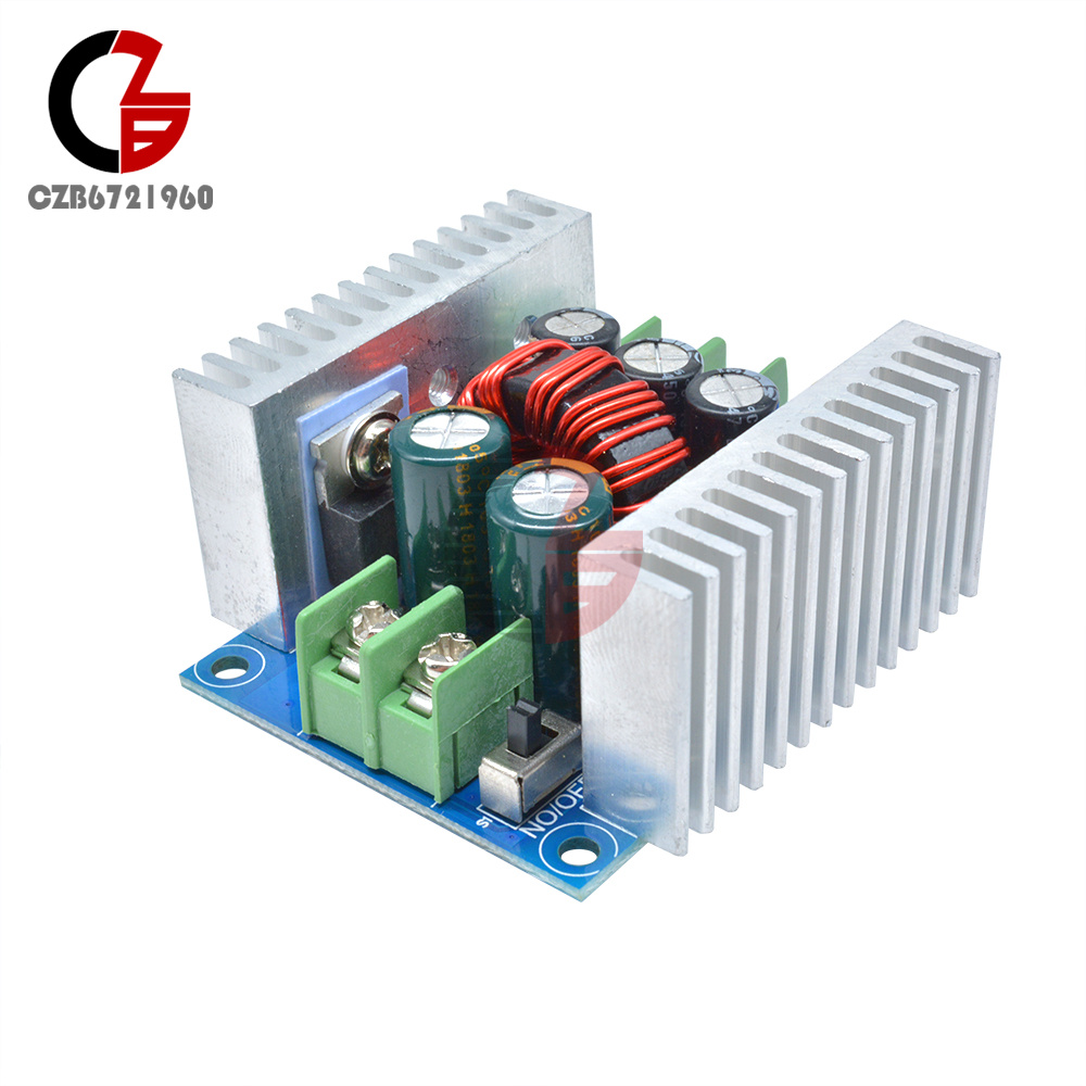
Module Type: Synchronous Rectification Non-Isolated Buck Constant Current Constant Voltage Module (CC/CV) Charging Module
Input Voltage: DC 10–40 V
Output Voltage: Continuously adjustable (1.2–32 VDC); sustained operation below 32 V (suitable for applications where the input voltage exceeds the output voltage; cannot boost voltage)
Output Current: 15 A (NAX)
Constant Current Range: 0.2–15 A (adjustable)
Minimum Voltage Drop: 3 V
Operating Frequency: 150 kHz
Conversion Efficiency: Up to approximately 96% (efficiency depends on voltage drop and operating environment)
Output Ripple: Approximately 50 mV (excluding noise), 20 MHz bandwidth (for reference only; measured with 24 V input)
Operating Temperature: -10°C to +75°C (Note: Monitor power transistor temperature during actual use; if temperature is too high, enhance cooling or derate the module)
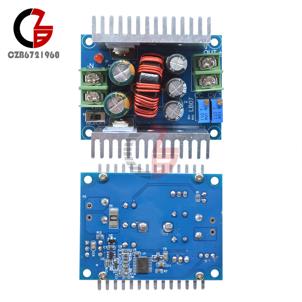
Potentiometer adjustment direction: Clockwise (increase), counterclockwise (decrease)
Output short-circuit protection: Yes (instantaneous protection). Constant current (the currently set constant current value must not be short-circuited for extended periods)
Input reverse connection protection: No
Output reverse current protection: No. An external diode is required for loads with built-in voltage or inductive loads!
Wiring method: Terminal blocks
Module Type: Synchronous Rectification Non-Isolated Buck Constant Current Constant Voltage Module (CC/CV) Charging Module
Input Voltage: DC 10–40 V
Output Voltage: Continuously adjustable (1.2–32 VDC); sustained operation below 32 V (suitable for applications where the input voltage exceeds the output voltage; cannot boost voltage)
Output Current: 15 A (NAX)
Constant Current Range: 0.2–15 A (adjustable)
Minimum Voltage Drop: 3 V
Operating Frequency: 150 kHz
Conversion Efficiency: Up to approximately 96% (efficiency depends on voltage drop and operating environment)
Output Ripple: Approximately 50 mV (excluding noise), 20 MHz bandwidth (for reference only; measured with 24 V input)
Operating Temperature: -10°C to +75°C (Note: Monitor power transistor temperature during actual use; if temperature is too high, enhance cooling or derate the module)
Potentiometer adjustment direction: Clockwise (increase), counterclockwise (decrease)
Output short-circuit protection: Yes (instantaneous protection). Constant current (the currently set constant current value must not be short-circuited for extended periods)
Input reverse connection protection: No
Output reverse current protection: No. An external diode is required for loads with built-in voltage or inductive loads!
Wiring method: Terminal blocks
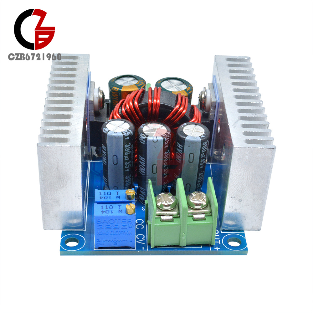
Output Current Adjustment Method:
1. Adjust the CV potentiometer to set the output voltage to the required value based on your load requirements.
2. Turn the CC potentiometer counterclockwise approximately 30 turns (i.e., set the output current to the minimum), connect the LED, then adjust the CC potentiometer to your desired current. For battery charging: Fully discharge the battery before connecting it to the output, then adjust the CC potentiometer to your desired current. (When charging, you must use a fully discharged battery for accurate calibration, as the remaining charge in the battery reduces the charging current.)
Package Contents:
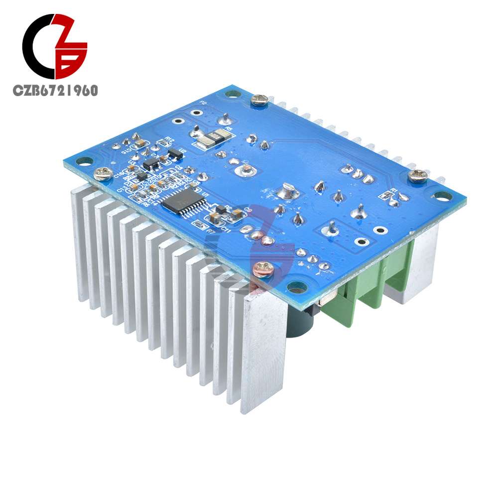
Step-down converter module
Step-down converter module
- We accept PayPal only. But we only Accept your Ebay Address,Please Make sure it's 100% right.
- Payment must be received in 5 business days of auction closing.
- Please leave note for your special request (e.g. Colors or Size) in PayPal when you pay the order.
- Any special request cannot be accepted after 24 hours of payment, because most of orders will be processed instantly and same day dispatched.
- We maintain high standards of excellence and strive for 100% customer satisfaction! Feedback is very important to us. We request that you contact us immediately BEFORE you give us neutral or negative feedback, so that we can satisfactorily address your concerns.
- All package need to wait 30 days(US only need 7-10 days),Please take care it.Less than 30 days,we can't take a refund.
- If the item is defect when you receive it or you are not satisfied with it, please return it within 14 days for a replacement or money back. But the items must be back in factory condition. Please contact us and double check the return address before you return it.
- If is item is defective in 12 months, you can return it to us. We will send you a new replacement after receiving the defective item.
On Apr 20, 2026 at 03:37:41 PDT, seller added the following information: