A) High-frequency signal generator
Frequency range ............ A 100KHz-300KHz
B 300KHz -1000KHz
C 1MHz --3.2MHz
D 3.0MHz --10MHz
E 10MHz -35MHz
F 32MHz --150MHz
(The third harmonic reaches 450MHz)
Frequency accuracy ... …………………… The reading accuracy is three digits after the decimal point.
High frequency output ........ 100mVrms, (about 35MHz)
Output control ........ 0dB / 20dB and fine adjustment
Modulation ................... Internal 1KHz
Crystal HC-6 / u seat ......................... For . 1 - 15MHz applied to HC-6 / u crystal holder used. (Not included)
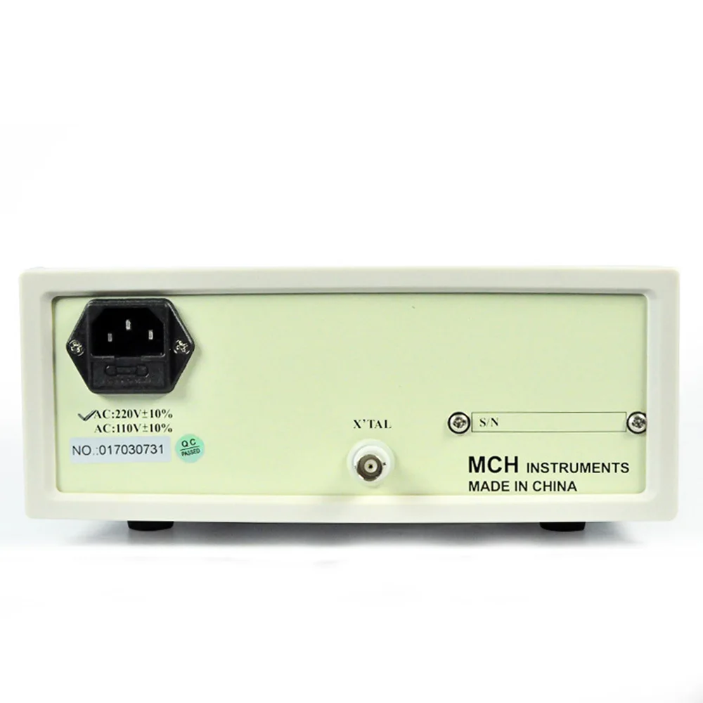
Power supply ……………………………… 220Vac ± 10% 50Hz
B) Frequency meter
Frequency range ……………………………… Low frequency 10Hz to 10MHz
High frequency 10MHz to 150MHz
Input voltage ……………………………… less than 50mV
Maximum input voltage ... …………………… about less than 3V effective value
Gate time ... …………………… 1s
Accuracy ……………………………… low frequency 1Hz / high frequency 10Hz
Input impedance ……………………………… low frequency 1M Ω / high frequency 50 Ω
Operating temperature ............ 0 to 40 ℃
2. 8-digit digital display of internal or external signal frequency
3. Built-in frequency meter, can measure external signal frequency 10Hz ~ 150MHz
4. Band internal and external modulation
Instructions for use
1. Ready to operate
1) The power switch is set to "OFF".
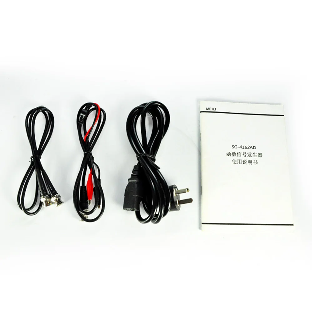
2) Connect the power cord and plug it in.
3) Connect the high-frequency signal output line to the "output" terminal.
4) Select the frequency range and adjust the frequency knob to reach the required frequency.
5) The output line should be as short as possible to avoid absorbing unwanted noise. Long shielded lines can reduce the frequency response of high frequency bands, especially when using square waves.
2. connection
When the signal wire is connected to the output, the red wire is high potential (or fire wire), the black wire is the ground wire and is connected to the chassis.
If high-frequency signals are to be connected to the antenna input of the receiver, a 50 to 200 Ω resistor should be connected in series. If receiving with a rod antenna, connect a coil with a few turns of wire on the test line to couple the signal to the antenna.
When detecting a high frequency and an intermediate frequency amplifying circuit, a middle to go through . 1 - 5pF small capacitance, in order to avoid detuning effect.
Note: When directly connecting the test circuit, make sure that there is no high DC voltage in the circuit under test. Otherwise, the frequency may be connected in series a 0.05 [mu] F. - 100pF capacitance.
packing list
Application / Application
SG-4162AD function signal generator is suitable for scientific research and experiment of electronic circuits and pulse circuits
| Performance parameter |
|
| output signal |
|
| Frequency Range |
A: 100kHz-300kHz B: 300kHz-1MHz C: 1MHz – 3.2MHz D: 3MHz – 10MHz E: 10MHz -35MHz F: 32MHz – 150 MHz 3rd harmonic up to 450MHz |
| Frequency accuracy |
± reading accuracy ± 1 digit |
| Output amplitude |
100mVrms (at 35MHz) |
| Amplitude control |
0dB, 20dB and trim |
| modulation |
In: 1kHz; Out: 50Hz - 20kHz (<1Vrms) |
| Audio output |
1kHz (fixed, ≥ 1Vrms) |
| frequency meter |
|
| Frequency Range |
Low frequency: 10Hz-10MHz High frequency: 10MHz – 150MHz |
| Sensitivity |
<50mV |
| input resistance |
Low frequency: 1M Ω High frequency: 50 Ω |
| Input voltage |
About <3V |
| General parameters |
|
| power supply |
AC 220V ± 10%, 50-60Hz (110V ± 10% optional) |
| working environment |
0 ℃ to 40 ℃ / ≤ 90% RH |
| size |
310 (W) x 100 (H) x 260 (D) mm |
| weight |
3.8kg |