descrizione
This product is a carrier board or breakout board for TI’s DRV8825 stepper motor driver; we therefore recommend careful reading of the DRV8825 datasheet before using this product. This stepper motor driver lets you control one bipolar stepper motor at up to 2.2 A output current per coil (see the Power Dissipation Considerations section below for more information). Here are some of the driver’s key features:
We also have a variety of other stepper motor driver options in this same form factor with different operating profiles and features.
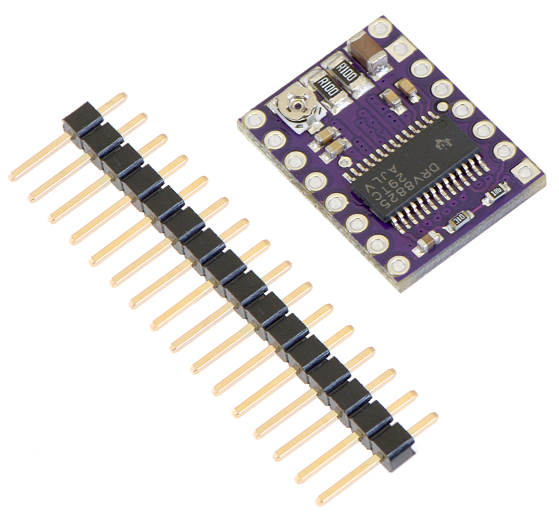
This product ships with all surface-mount components—including the DRV8825 driver IC—installed as shown in the product picture.
This product ships individually packaged with 0.1″ male header pins included but not soldered in; we also carry a version with male header pins already soldered in. For customers interested in higher volumes at lower unit costs, we offer a bulk-packaged version without header pins and a bulk-packaged version with header pins installed.
Some unipolar stepper motors (e.g. those with six or eight leads) can be controlled by this driver as bipolar stepper motors. For more information, please see the frequently asked questions. Unipolar motors with five leads cannot be used with this driver.
Included hardware
The DRV8825 stepper motor driver carrier ships with one 1×16-pin breakaway 0.1" male header. The headers can be soldered in for use with solderless breadboards or 0.1" female connectors. You can also solder your motor leads and other connections directly to the board. (A version of this board with headers already installed is also available.)
|
|
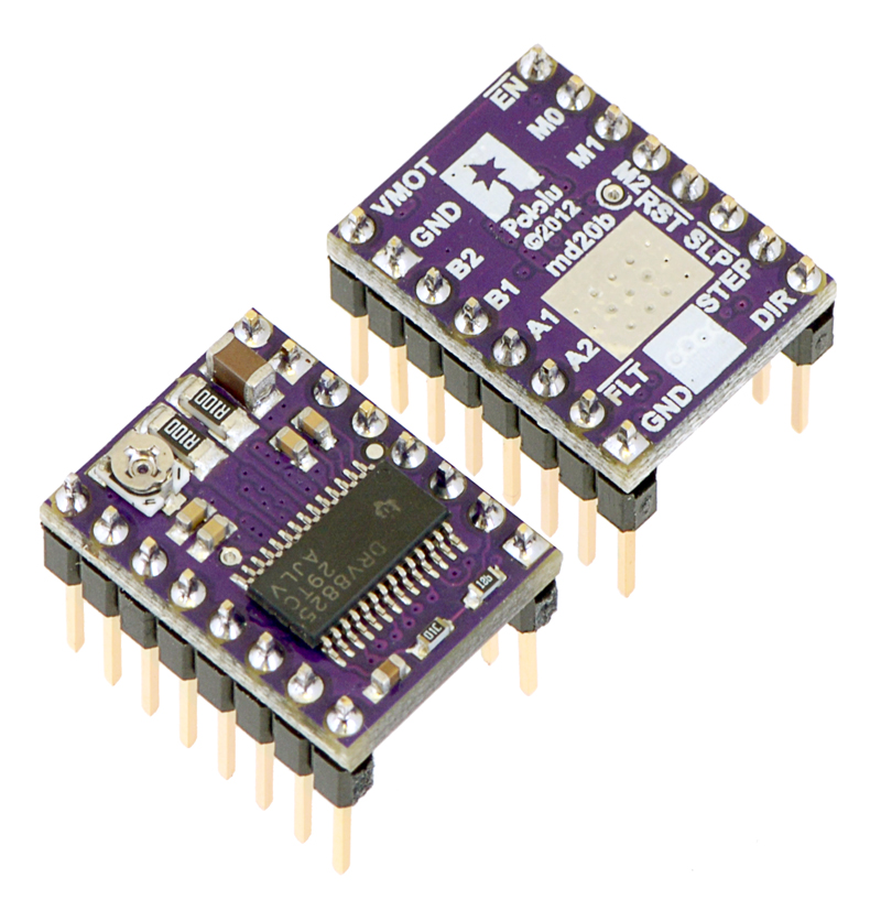
Caution: Installing the header pins so that the silkscreen side is up and the components are down can limit the range of motion of the trimpot used to set the current limit. If you plan on installing the header pins in this orientation, please set the current limit before soldering in the pins.
Using the driver
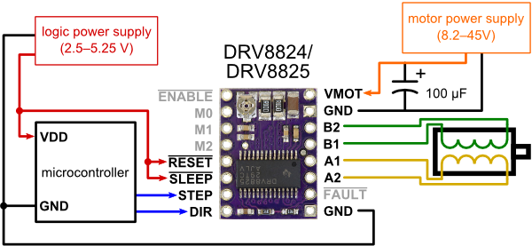 |
Minimal wiring diagram for connecting a microcontroller to a DRV8824/DRV8825 stepper motor driver carrier (full-step mode). |
|---|
Power connections
The driver requires a motor supply voltage of 8.2 – 45 V to be connected across VMOT and GND. This supply should have appropriate decoupling capacitors close to the board, and it should be capable of delivering the expected stepper motor current.
Warning: This carrier board uses low-ESR ceramic capacitors, which makes it susceptible to destructive LC voltage spikes, especially when using power leads longer than a few inches. Under the right conditions, these spikes can exceed the 45 V maximum voltage rating for the DRV8825 and permanently damage the board, even when the motor supply voltage is as low as 12 V. One way to protect the driver from such spikes is to put a large (at least 47 µF) electrolytic capacitor across motor power (VMOT) and ground somewhere close to the board.
Motor connections
Four, six, and eight-wire stepper motors can be driven by the DRV8825 if they are properly connected; a FAQ answer explains the proper wirings in detail.
Warning: Connecting or disconnecting a stepper motor while the driver is powered can destroy the driver. (More generally, rewiring anything while it is powered is asking for trouble.)
Step (and microstep) size
Stepper motors typically have a step size specification (e.g. 1.8° or 200 steps per revolution), which applies to full steps. A microstepping driver such as the DRV8825 allows higher resolutions by allowing intermediate step locations, which are achieved by energizing the coils with intermediate current levels. For instance, driving a motor in quarter-step mode will give the 200-step-per-revolution motor 800 microsteps per revolution by using four different current levels.
The resolution (step size) selector inputs (MODE0, MODE1, and MODE2) enable selection from the six step resolutions according to the table below. All three selector inputs have internal 100kΩ pull-down resistors, so leaving these three microstep selection pins disconnected results in full-step mode. For the microstep modes to function correctly, the current limit must be set low enough (see below) so that current limiting gets engaged. Otherwise, the intermediate current levels will not be correctly maintained, and the motor will skip microsteps.
| MODE0 | MODE1 | MODE2 | Microstep Resolution |
|---|---|---|---|
| Low | Low | Low | Full step |
| High | Low | Low | Half step |
| Low | High | Low | 1/4 step |
| High | High | Low | 1/8 step |
| Low | Low | High | 1/16 step |
| High | Low | High | 1/32 step |
| Low | High | High | 1/32 step |
| High | High | High | 1/32 step |
Control inputs
Each pulse to the STEP input corresponds to one microstep of the stepper motor in the direction selected by the DIR pin. These inputs are both pulled low by default through internal 100kΩ pull-down resistors. If you just want rotation in a single direction, you can leave DIR disconnected.
The chip has three different inputs for controlling its power states: RESET, SLEEP, and ENBL. For details about these power states, see the datasheet. Please note that the driver pulls the SLEEP pin low through an internal 1MΩ pull-down resistor, and it pulls the RESET and ENBL pins low through internal 100kΩ pull-down resistors. These default RESET and SLEEP states are ones that prevent the driver from operating; both of these pins must be high to enable the driver (they can be connected directly to a logic “high” voltage between 2.2 and 5.25 V, or they can be dynamically controlled via connections to digital outputs of an MCU). The default state of the ENBL pin is to enable the driver, so this pin can be left disconnected.
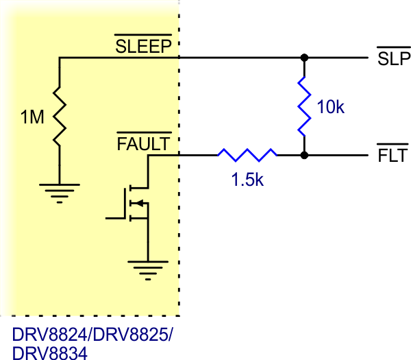 |
Schematic of nSLEEP and nFAULT pins on DRV8824/DRV8825/DRV8834 carriers. |
|---|
The DRV8825 also features a FAULT output that drives low whenever the H-bridge FETs are disabled as the result of over-current protection or thermal shutdown. The carrier board connects this pin to the SLEEP pin through a 10k resistor that acts as a FAULT pull-up whenever SLEEP is externally held high, so no external pull-up is necessary on the FAULT pin. Note that the carrier includes a 1.5k protection resistor in series with the FAULT pin that makes it is safe to connect this pin directly to a logic voltage supply, as might happen if you use this board in a system designed for the pin-compatible A4988 carrier. In such a system, the 10k resistor between SLEEP and FAULT would then act as a pull-up for SLEEP, making the DRV8825 carrier more of a direct replacement for the A4988 in such systems (the A4988 has an internal pull-up on its SLEEP pin). To keep faults from pulling down the SLEEP pin, any external pull-up resistor you add to the SLEEP pin input should not exceed 4.7k.