Good News:
New items have arrived our USA Warehouse,welcome you to purchase.

Package include:
- 1 x 4 Axis CNC Motion Controller System (DDCSV3.1)
- 1 x 4 Axis 100PPR Pendant Handwheel with emergency stop with connection plug
- 1 x 4GB USB Flash drive
- 1 x USB Extension Cable
- User manual will send by email


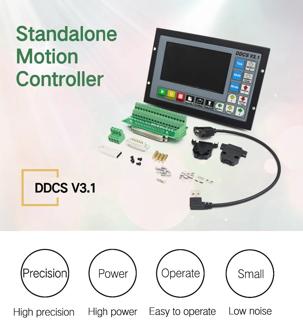

DDCS V3.1 Controller Brief Introduction
1.1 Introduction of Product
The DDCS is a 3~4 axis motion controller for stepper and servo systems. DDCS V3.1 is updated from DDCS V2.1 on software and hardware.It combines great power with a tiny footprint and is easy to use. The highest output pulse per axis is 500KHz. This provides high control precision for stepper motors and servo motors.
The DDCS numerical control system adopts the ARM+FPGA design framework. ARM controls the human-computer interface and code analysis and the FPGA provides the underlying algorithms and creates the control pulse. This guarantees reliable control and easy operation. The internal operating system is Linux based. The panel layout structure of the DDCS V3.1 is very rational to save space. All operations are controlled by only 17 keys and a comprehensive G code set is supported. The DDCS can be used for many styles and types of CNC machines. Lathes, Routers, Pick&- Place and Mills are just a few examples.
The DDCS operates as a Stand Alone system without the need of a computer. This guarantees high precision, accuracy and reliability. The interface, even very comprehensive, can be learned in a very short time.
1.2 DDCS V3.1 Brief technical feature:
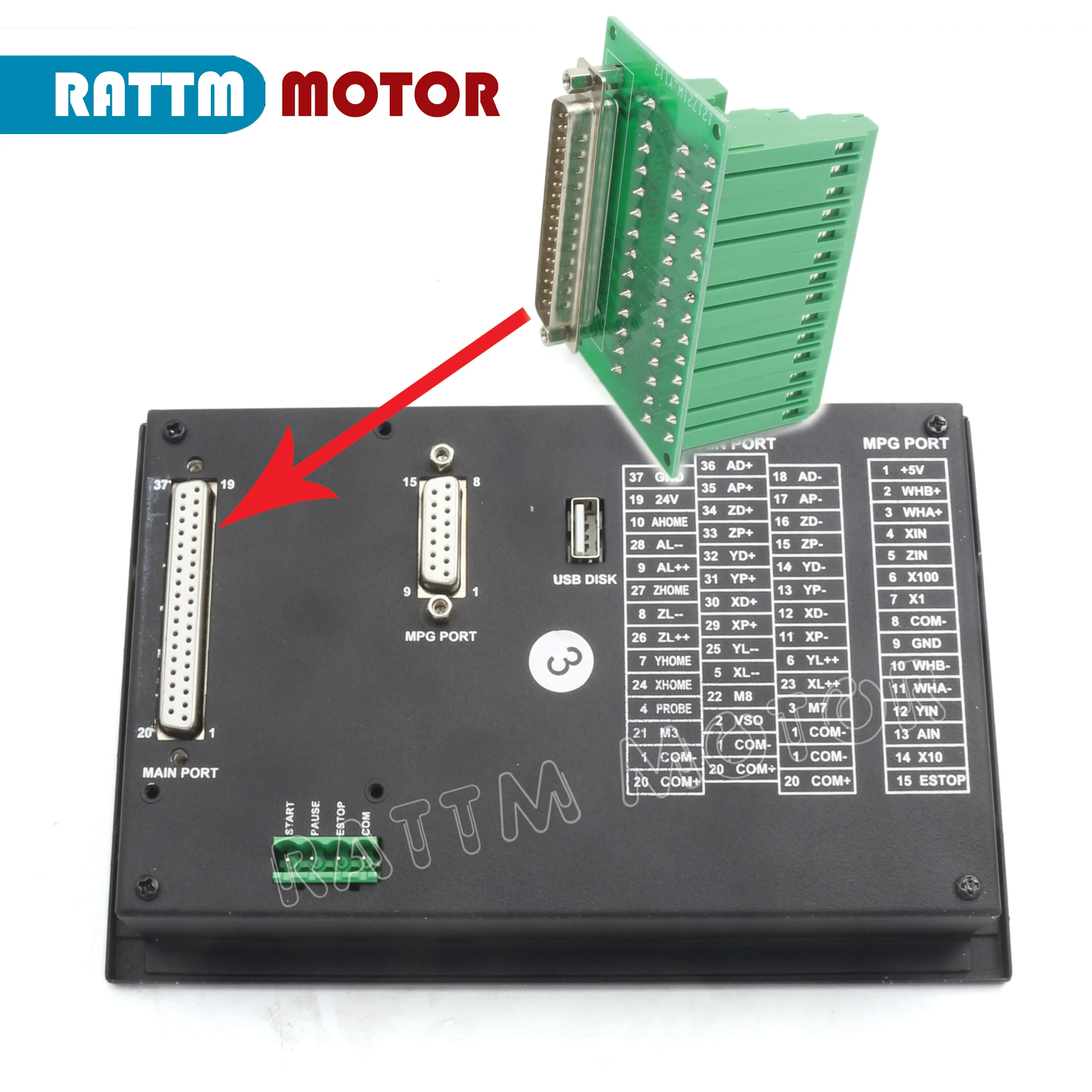
1) 16 photoelectric isolated digital inputs,3 photoelectric isolated digital outputs;
2) 3.1 Version enhenced Algorithm,support soft interpolation,fixed arc interpolation bug of the old version;
3) Analog spindle control 0-10V spindle control (can be modified as PWM output);
4) 3-4 axis motor Control.Differential Pulse and direction output signal,Max.500Khz per axis;
5) ARM9 main control chip,FPGA core algorithm chip;
6) 5 inches TFT screen, resolution ratio: 480x272,17 operation keys;
7) The Power Supply for the controller is 24VDC, minimum Current is 0.5A;
8) The Power Supply for IO Port is 24VDC,minimum current is 0.5A;By the IO power supply,system already supply the power for IO ports.So no need the external power supply for IO port anymore;
9) USB flash disk support for G code file input,no size limited of the G-code file ;
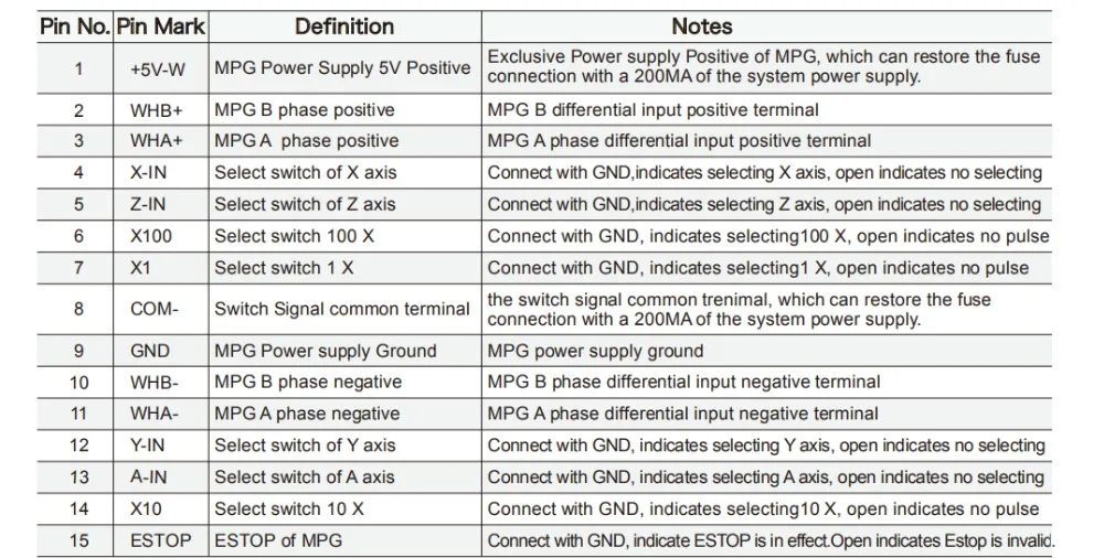
10) Support standard MPG;
11) Jog function for each axis (continuous, step, defined distance);Customer can define the distance;
12) Support the operation of quickly specify the running position;
13) Support for “Power Cut” recovery. Data is automatically saved;
14) The controller only support NPN type limited switch.
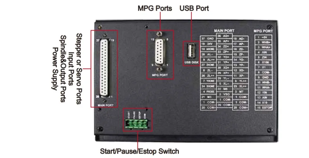
1.3 Appearance, Structure and Size of Product
The
DDCS V3.1 is a small box that can fit in a window of a small control
box or control cabinet. Four locking hooks fix this controller from the
frame. The dimension you find in picture 1-1 and picture 1-2. The front
panel is 191mm*128mm*5mm; The main body is 191mm*128mm*37mm; To mount
the unit in an equipment cabinet, cut the hole182.5mm*59mm

1.3 Appearance, Structure and Size of Product
The DDCS V3.1 is a small box that can fit in a window of a small control box or control cabinet. Four locking hooks fix this controller from the frame. The dimension you find in picture 1-1 and picture 1-2. The front panel is 191mm*128mm*5mm; The main body is 191mm*128mm*37mm; To mount the unit in an equipment cabinet, cut the hole182.5mm*59mm
|
|
|
|---|---|---|
The Limit wiring at X++ direction with mechanical limited switch
| Power Supply Input
| Spindle control output
|


|
|
|
|---|---|---|
Stepper/Servo Control Output
| The Limit wiring at X++ direction with 3-line proximity switch
| The Probe Wiring
|


Outward Appearance,Structure and Size

4 Axis MPG Pendant Handwheel with Emergency stop with 15-pin plug

The CNC 4 Axis handheld controller MPG Pendant with x1, x10, x100 selectable, You are bidding one complete unit of the MPG pendant with Emergency stop for 4 axis CNC machine,it equipped with our popular machined MPG unit with 4 axis and scale selector, LED indicator also send feedback from the CNC machine to user about the status of the unit.
Plug and play, this MPG comes with a 15-pin plug, which can be directly connected to the 15-pin socket of the controller MPG.
- x1, x10, x100 switch
- X,Y,Z,4th axis selector switch
- LED indicator
- With Emergency stop
- High quality professional chassis
- Extendable high quality shielded cable cord
- Magnetic base holder can place anywhere on the machine steel surface
- Required 5V+, 150mA, power for MPG
- Resolution:100PPR
- Supply Current:≤80mA
- Output Voltage:≥2.5V and ≤0.4V
- Fall/Rise time:≤5ns(typ)
- Response Frequency:0-10KHz
Shipping
1.Items will be shipped within 1-2 days upon the receipt of payment.
2.Please check out your address carefully when processing order.We are not responsible for wrong or undeliverable address.
We will ship item to your PAYPAL address. If other address, please advise us by eBay or E-mail.
3.The estimated delivery time is 7~15 workings days to Asian, USA, AU, UK and most western European countries;
15~30 workings days to most other countries.
Return&Refund
1.Any reason required for all refund.Item must be in it's original condition and no physical damage,buyer responsible for all shipping cost.
2.When you have the parcel,and not satisfied the goods or it is other problem like as broken,pls tell us the detail reason and provide the photos,we will help you to solve any problems.
Contact
1.If you are not satisfied, please contact us to resolve any issues. Please do NOT leave negative feedback without asking for help. We work hard to make sure EVERY CUSTOMER 100% satisfaction.
2.For any inquiries,issues or assistanceplease contact us via eBay or leave your mail address.
3.All emails will be answered within 1-2 working days.If you do not receive our reply,please kindly re-send your email and we will reply to you as soon as possible.
